Automatic disconnection of supply is an interruption of one or more of the line conductors effected by the automatic operation of a protective device in the event of a fault (Source: IEC 61140-2016).
Automatic disconnection of supply is a protective measure in which:
NOTE 1. Where this protective measure is applied, Class II equipment may also be used.
Where specified, additional protection is provided by a residual current protective device (RCD) with rated residual operating current not exceeding 30 mA.
NOTE 2. Residual current monitors (RCMs) are not protective devices but they may be used to monitor residual currents in electrical installations. RCMs produce an audible or audible and visual signal when a preselected value of residual current is exceeded.
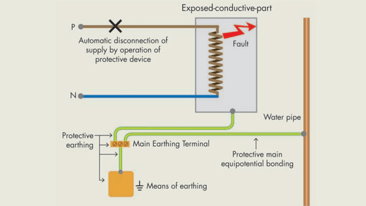 Example – Automatic Disconnection of Supply
All electrical equipment shall comply with one of the provisions for basic protection. Provisions for basic protection provide protection under normal conditions and are applied where specified as a part of the chosen protective measure.
NOTE. The insulation is intended to prevent contact with live parts.
Live parts shall be completely covered with insulation which can only be removed by destruction.
For equipment, the insulation shall comply with the relevant standard for the electrical equipment.
NOTE. Barriers or enclosures are intended to prevent contact with live parts.
Live parts shall be inside enclosures or behind barriers providing at least the degree of protection IPXXB or IP2X except that, where larger openings occur during the replacement of parts, such as certain lampholders or fuses, or where larger openings are necessary to allow the proper functioning of equipment according to the relevant requirements for the equipment:
- suitable precautions shall be taken to prevent persons or livestock from unintentionally touching live parts, and
- it shall be ensured, as far as practicable, that persons will be aware that live parts can be touched through the opening and should not be touched intentionally, and
- the opening shall be as small as is consistent with the requirement for proper functioning and for replacement of a part.
Horizontal top surfaces of barriers or enclosures which are readily accessible shall provide a degree of protection of at least IPXXD or IP4X.
Barriers and enclosures shall be firmly secured in place and have sufficient stability and durability to maintain the required degrees of protection and appropriate separation from live parts in the known conditions of normal service, taking account of relevant external influences.
Where it is necessary to remove barriers or open enclosures or to remove parts of enclosures, this shall be possible only:
- by the use of a key or tool, or
- after disconnection of the supply to live parts against which the barriers or enclosures afford protection, restoration of the supply being possible only after replacement or reclosure of the barriers or enclosures, or
- where an intermediate barrier providing a degree of protection of at least IPXXB or IP2X prevents contact with live parts, by the use of a key or tool to remove the intermediate barrier.
If, behind a barrier or in an enclosure, items of equipment are installed which may retain dangerous electrical charges after they have been switched off (capacitors, etc.), a warning label is required. Small capacitors such as those used for arc extinction, for delaying the response of relays, etc shall not be considered dangerous.
NOTE. Unintentional contact is not considered dangerous if the voltage resulting from static charges fall below 120 V d.c. in less than 5 s after disconnection from the power supply.
Exposed-conductive-parts shall be connected to a protective conductor under the specific conditions for each type of system earthing.
Simultaneously accessible exposed-conductive-parts shall be connected to the same earthing system individually, in groups or collectively.
Conductors for protective earthing shall comply with IEC 60364-5-54.
Each circuit shall have available a protective conductor connected to the relevant earthing terminal.
In each building, incoming metallic parts which are liable to introduce a dangerous potential difference and do not form part of the electrical installation shall be connected to the main earthing terminal by protective bonding conductors; examples of such metallic parts may include:
- pipes supplying services into the building, for example gas, water, district heating systems;
- structural extraneous-conductive-parts;
- accessible reinforcement of constructional reinforced concrete.
Where such conductive parts originate outside the building, they shall be bonded as close as practicable to their point of entry within the building.
Metallic pipes entering the building having an insulating section installed at their entrance need not be connected to the protective equipotential bonding.
A protective device shall automatically switch off the supply to the line conductor of a circuit or equipment in the event of a fault of negligible impedance between the line conductor and an exposed conductive-part or a protective conductor in the circuit or equipment within the disconnection time.
The device shall be suitable for isolation of at least the line conductor(s).
NOTE. For IT systems, automatic disconnection is not necessarily required on the occurrence of a first fault.
The maximum disconnection time stated in Table 1 shall be applied to final circuits with a rated current not exceeding:
- 63 A with one or more socket-outlets, and
- 32 A supplying only fixed connected current-using equipment.
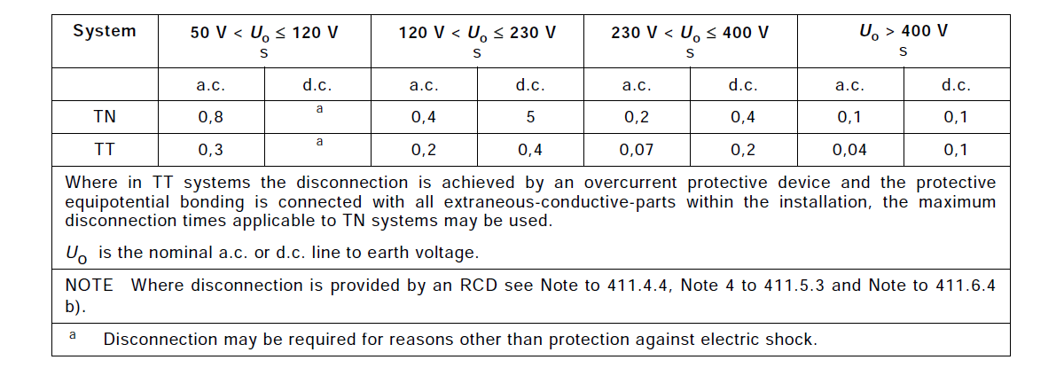 Table 1 – Maximum disconnection times (source: Table 41.1 of IEC 60364-4-41-2017)
NOTE. In Belgium, the maximum discontinuation time is not applicable; the Belgian safety curve as given in the Belgian Wiring Rules needs to be followed.
NOTE. In the Netherlands the maximum disconnection time stated in Table 1 is applied to all circuits not exceeding 32 A and all circuits supplying socket-outlets.
NOTE. In Austria TT-systems for nominal voltages to earth Uo exceeding 230 V are not permitted. Therefore the values of column 6 to 10 in line 4 are not applicable.
In TN systems, a disconnection time not exceeding 5 s is permitted for distribution circuits.
In TT systems, a disconnection time not exceeding 1 s is permitted for distribution circuits.
Additional protection by means of a residual current protective device (RCD) with a rated residual operating current not exceeding 30 mA shall be provided for:
- a.c. socket-outlets with a rated current not exceeding 32 A that are liable to be used by ordinary persons and are intended for general use; and
- a.c. mobile equipment for use outdoors with a rated current not exceeding 32 A.
This subclause does not apply for IT systems in which the fault current, in the event of a first fault, does not exceed 15 mA.
NOTES:
In the United Kingdom additional protection by means of an RCD is required to be provided for:
(i) socket-outlets with a rated current not exceeding 20 A, and
(ii) mobile equipment with a current rating not exceeding 32 A for use outdoors.
In Ireland additional protection is provided for socket-outlets with a rated current up to 32 A intended for use by ordinary persons.
In Belgium, every electrical installation under the supervision of ordinary persons must be protected by a RCD with a rated operating residual current not exceeding 300 mA. For circuits supplying bathrooms, washing machines, dishwashers, etc, an additional protection by means of a RCD with a rated residual operating current not exceeding 30 mA is mandatory. The above is valid for electrical installations whose earthing resistance is lower than 30 Ω. In case of earthing resistance higher than 30 Ω and lower than 100 Ω, additional RCDs with a rated operating residual current not exceeding 100 mA should be provided. An earthing resistance higher than 100 Ω is not permitted.
In Norway all commercial and industrial companies are covered by regulations requiring procedures for qualifications and training of employees. Except for areas open for the public, socket-outlets in such locations are normally not considered to be for general use of ordinary people. Socket-outlets in dwellings and BA2 locations are intended for general use by ordinary people.
In premises designed to accommodate a single household, additional protection by a residual current protective device (RCD) with a rated residual operating current not exceeding 30 mA shall be provided for a.c. final circuits supplying luminaires.
NOTE. In Belgium, this requirement is not applicable.
In TN systems the integrity of the electrical earthing of the installation depends on the reliable and effective connection of the PEN or PE conductors to earth. Where the earthing is provided from a public or other supply system, compliance with the necessary conditions external to the installation is the responsibility of the supply network operator.
NOTE. Examples of conditions include:
- the PEN is connected to earth at a number of points and is installed in such a way as to minimize the risk arising from a break in the PEN conductor;
- RB/RE ≤ 50/(U0 – 50)
where
RB is the earth electrode resistance, in ohms, of all earth electrodes in parallel;
RE is the minimum contact resistance with earth, in ohms, of extraneous-conductive-parts not connected to a protective conductor, through which a fault between line and earth may occur;
Uo is the nominal a.c. r.m.s. voltage to earth, in volts.
NOTE. In Germany, it is mandatory for DSOs to fulfil the conditions of the formula given in the Note.
NOTE. In Germany, every new building shall have a foundation earth electrode, erected in accordance with DIN 18014.
NOTE. In Austria, in a TN system every installation shall have an earth electrode. In Austria a foundation earth electrode shall be erected according OVE/ÖNORM E 8014.
NOTE. In Switzerland a foundation earth electrode shall be erected according to SNR 464113.
The neutral point or the midpoint of the power supply system shall be earthed. If a neutral point or midpoint is not available or not accessible, a line conductor shall be earthed.
Exposed-conductive-parts of the installation shall be connected by a protective conductor to the main earthing terminal of the installation which shall be connected to the earthed point of the power supply system.
If other effective earth connections exist, it is recommended that the protective conductors also be connected to such points wherever possible. Earthing at additional points, distributed as evenly as possible, may be necessary to ensure that the potentials of protective conductors remain, in case of a fault, as near as possible to that of earth.
It is recommended that protective conductors (PE and PEN) should be earthed where they enter any buildings or premises taking account of any diverted neutral currents of multiple earthed PEN conductors.
In fixed installations, a single conductor may serve both as a protective conductor and as a neutral conductor (PEN conductor) provided that the requirements of 543.4 of IEC 60364-5-54 are satisfied. No switching or isolating device shall be inserted in the PEN conductor.
NOTE 1. In Switzerland the main building overcurrent protective device with integrated isolating device in the PEN conductor forms the interface between the network and the installation of the building.
NOTE 2. In Norway, the use of a PEN conductor downstream of the main distribution board is not allowed.
The characteristics of the protective devices and the circuit impedances shall fulfil the following requirement:
Zs × Ia ≤ Uo
where
Zs is the impedance in ohms (Ω) of the fault loop comprising:
– the source,– the line conductor up to the point of the fault, and
– the protective conductor between the point of the fault and the source;
Ia is the current in amperes (A) causing the automatic operation of the disconnecting device within disconnection time. When a residual current protective device (RCD) is used this current is the residual operating current providing disconnection in the time.
Uo is the nominal a.c. or d.c. line to earth voltage in volts (V).
NOTE. In TN systems the residual fault currents are significantly higher than 5 IΔn. Therefore, the disconnection times in accordance with Table 1 are fulfilled where residual current protective devices (RCDs) according to IEC 61008-1, IEC 61009-1 or IEC 62423, including selective and time delayed types, are installed. Circuit-breakers providing residual current protection (CBR) and MRCDs according to IEC 60947-2 can be used, provided the time delay is adjusted to afford compliance with Table 1.
In TN systems, the following protective devices may be used for fault protection (protection against indirect contact):
- overcurrent protective devices;
- residual current protective devices (RCDs).
NOTE 1. Where an RCD is used for fault protection the circuit should also be protected by an overcurrent protective device in accordance with IEC 60364-4-43.
A residual current protective device (RCD) shall not be used in TN-C systems.
NOTE 2. Where discrimination between RCDs is necessary, see 535.3 of IEC 60364-5-53.
All exposed-conductive-parts collectively protected by the same protective device shall be connected by the protective conductors to an earth electrode common to all those parts. Where several protective devices are utilized in series, this requirement applies separately to all the exposed-conductive-parts protected by each device.
The neutral point or the mid-point of the power supply system shall be earthed. If a neutral point or mid-point is not available or not accessible, a line conductor shall be earthed.
NOTE. In the Netherlands the resistance of the earth electrode should be as low as practicable, but in any case not exceeding 166 Ω.
Generally in TT systems, RCDs shall be used for fault protection. Alternatively, overcurrent protective devices may be used for fault protection provided a suitably low value of Zs is permanently and reliably assured.
NOTE 1. Where an RCD is used for fault protection the circuit should also be protected by an overcurrent protective device in accordance with IEC 60364-4-43.
NOTE 2. In Italy, in case of TT systems, only RCDs shall be used for fault protection.
Where a residual current protective device (RCD) is used for fault protection, the following conditions shall be fulfilled:
- the disconnection time
- RA x IΔn ≤ 50 V
where
– RA is the sum of the resistance in Ω of the earth electrode and the protective conductor for the exposed conductive-parts,
– IΔn is the rated residual operating current of the RCD.
NOTE 1. Fault protection is provided in this case also if the fault impedance is not negligible.
NOTE 2. Where discrimination between RCDs is necessary see 535.3 of IEC 60364-5-53.
NOTE 3. Where RA is not known, it may be replaced by ZS.
NOTE 4. The disconnection times in accordance with Table 1 relate to prospective residual fault currents significantly higher than the rated residual operating current of the RCD (typically 5 IΔn).
Where an overcurrent protective device is used the following condition shall be fulfilled:
Zs × Ia ≤ Uo
where
Zs is the impedance in Ω of the fault loop comprising
− the source,− the line conductor up to the point of the fault,− the protective conductor of the exposed-conductive-parts,− the earthing conductor,− the earth electrode of the installation and
− the earth electrode of the source;
Ia is the current in A causing the automatic operation of the disconnecting device within disconnection time.
Uo is the nominal a.c. or d.c. line to earth voltage.
In IT systems live parts shall be insulated from earth or connected to earth through a sufficiently high impedance. This connection may be made either at the neutral point or midpoint of the system or at an artificial neutral point. The latter may be connected directly to earth if the resulting impedance to earth is sufficiently high at the system frequency. Where no neutral point or mid-point exists, a line conductor may be connected to earth through a high impedance.
The fault current is then low in the event of a single fault to an exposed-conductive-part or to earth and automatic disconnection is not imperative provided the condition in subclause “Automatic disconnection in case of a fault” is fulfilled. Provisions shall be taken, however, to avoid risk of harmful pathophysiological effects on a person in contact with simultaneously accessible exposed-conductive-parts in the event of two faults existing simultaneously.
NOTE 1. To reduce overvoltage or to damp voltage oscillation, it may be necessary to provide earthing through impedances or artificial neutral points, and the characteristics of these should be appropriate to the requirements of the installation.
NOTE 2. In Norway, where more installations are likely to have galvanic connection to the same distribution network, all final circuits in IT installations with galvanic connection to a public IT distribution network need to be disconnected within the time specified for a TN system (see Table 1) in the event of a fault of negligible impedance between the line conductor and an exposed-conductive-part or a protective conductor in the circuit or
equipment.
Exposed-conductive-parts shall be earthed individually, in groups, or collectively.
The following condition shall be fulfilled:
In a.c. systems the following condition shall be fulfilled to limit the touch voltage to:
RA × Id ≤ 50 V
where
- RA is the sum of the resistance in Ω of the earth electrode and protective conductor for the exposed-conductive-parts;
- Id is the fault current in A of the first fault of negligible impedance between a line conductor and an exposed-conductive-part. The value of Id takes account of leakage currents and the total earthing impedance of the electrical installation.
NOTE. No touch voltage limitation is considered in d.c. systems as the value of Id can be considered to be negligibly low.
In IT systems the following monitoring devices and protective devices may be used:
- insulation monitoring devices (IMDs);
- residual current monitoring devices (RCMs)
- insulation fault location systems (IFLS);
- overcurrent protective devices;
- residual current protective devices (RCDs).
NOTE 1. Where a residual current protective device (RCD) is used, tripping of the RCD in the event of a first fault cannot be excluded due to capacitive leakage currents.
NOTE 2. In case of faults in two different items of class I current-using equipment supplied by different line conductors, the operation of a residual current protective device (RCD) is only likely to be achieved if every single item of current using equipment is protected by an individual residual protective device (RCD). The use of overcurrent protective devices to provide fault protection is also suitable.
Where an IT system is designed not to disconnect in the event of first fault, the occurrence of the first fault shall be indicated by either:
- an insulation monitoring device (IMD), which may be combined with an insulation fault location system (IFLS), or
- a residual current monitor (RCM), provided the residual current is sufficiently high to be detected.
NOTE. RCMs are not able to detect symmetrical insulation faults.
This device shall initiate an audible and/or visual signal which shall continue as long as the fault persists. The signal can be initiated via a relay contact output, an electronic switching output or a communication protocol.
A visual and/or an audible alarm system shall be arranged at a suitable place, so that it is perceived by responsible persons.
If there are both audible and visible signals, it is permissible for the audible signal to be cancelled.
It is recommended that a first fault be eliminated with the shortest practicable delay.
In addition, an insulation fault location system (IFLS) according to IEC 61557-9 may be provided to indicate the location of a first fault from a live part to exposed-conductive-parts or earth or another reference point.
After the occurrence of a first fault, conditions for automatic disconnection of supply in the event of a second fault occurring on a different live conductor shall be as follows:
a) Where exposed-conductive-parts are interconnected by a protective conductor collectively earthed to the same earthing system, the conditions similar to a TN system apply and the following conditions shall be fulfilled where the neutral conductor is not distributed in a.c. systems and in d.c. systems where the mid-point conductor is not distributed:
2*IaZs ≤ U
or where the neutral conductor or mid-point conductor respectively is distributed:
2*IaZ’s ≤ Uo
where
Uo is the nominal a.c. or d.c. voltage, in V, between line conductor and neutral conductor or mid-point conductor, as appropriate;U is the nominal a.c. or d.c. voltage in V between line conductors;
Zs is the impedance in Ω of the fault loop comprising the line conductor and the protective conductor of the circuit;
Z′s is the impedance in Ω of the fault loop comprising the neutral conductor and the protective conductor of the circuit;
Ia is the current in A causing the automatic operation of the disconnecting device within disconnection time.
NOTE 1. The time stated in Table 1 for the TN system is applicable to IT systems with a distributed or non-distributed neutral conductor or mid-point conductor.
NOTE 2. The factor 2 in both formulas takes into account that in the event of the simultaneous occurrence of two faults, the faults may exist in different circuits.
NOTE 3. For fault loop impedance, the most severe case should be taken into account, e.g. a fault on the line conductor at the source and simultaneously another fault on the neutral conductor of a current-using equipment of the circuit considered.
b) Where the exposed-conductive-parts are earthed in groups or individually, the following condition applies:
RA × Ia ≤ 50 V
where
RA is the sum of the resistances of the earth electrode and the protective conductor to the exposed-conductive-parts,
Ia is the current causing automatic disconnection of the disconnection device in a time complying to that for TT systems in Table 1.
NOTE 4. If compliance to the requirements of b) is provided by a residual current protective device (RCD) compliance with the disconnection times required for TT systems in Table 1 may require residual currents significantly higher than the rated residual operating current IΔn of the RCD applied (typically 5 IΔn).
Where, for functional reasons, a nominal voltage not exceeding 50 V a.c. or 120 V d.c. is used but all the requirements of Clause 414 of IEC 60364-4-41-2017 relating to SELV or to PELV are not fulfilled, and where SELV or PELV is not necessary, the supplementary provisions shall be taken to ensure basic protection and fault protection. This combination of provisions is known as FELV.
NOTE. Such conditions may, for example, be encountered when the circuit contains equipment (such as transformers, relays, remote-control switches, contactors) insufficiently insulated with respect to circuits at higher voltage.
Basic protection shall be provided by either:
- basic insulation corresponding to the nominal voltage of the primary circuit of the source, or
- barriers or enclosures.
The exposed-conductive-parts of the equipment of the FELV circuit shall be connected to the protective conductor of the primary circuit of the source, provided that the primary circuit is subject to protection by automatic disconnection of supply.
The source of the FELV system shall be either a transformer with at least simple separation between windings or shall comply with 414.3 of IEC 60364-4-41-2017.
NOTE. If the system is supplied from a higher voltage system by equipment which does not provide at least simple separation between that system and the FELV system, such as autotransformers, potentiometers, semiconductor devices, etc., the output circuit is deemed to be an extension of the input circuit and should be protected by the protective measure applied in the input circuit.
Plugs and socket-outlets for FELV systems shall comply with all the following requirements:
- plugs shall not be able to enter socket-outlets of other voltage systems,
- socket-outlets shall not admit plugs of other voltage systems, and
- socket-outlets shall have a protective conductor contact.
Devices used for automatic disconnection of supply shall be placed at the origin or upstream of the circuit which is intended to be protected.
These devices shall be suitable for isolation.
NOTE 1: Protective devices which require manual operation in order to achieve isolation are not excluded.
The following protective devices may be used:
- overcurrent protective devices;
- residual current protective devices (RCDs).
Devices according to IEC 60947-2 identified with voltage value(s) followed by the symbol  (IEC 60417-6363:2016-07-16) or by the symbol
  shall not be used in IT systems for such voltage(s) or above.
Devices according to IEC 60947-2 identified with the symbol (IEC 60417-6363:2016-07-16) or by the symbol with no associated voltage value, shall not be used in IT systems.
NOTE 2: The symbol previously required will be progressively superseded by the preferred new symbol above.