Electrical symbols play a critical role in electrical engineering and design by providing a standardized language for representing various components, devices, and connections in circuit diagrams and schematics. Electrical symbols and electronic circuit symbols are used to illustrate schematic diagrams. These symbolic representations effectively depict various electrical and electronic components, making it easier for engineers, technicians, and electricians to understand, analyze, and communicate complex electrical systems.
| Symbol | Component name | Meaning |
|---|---|---|
| → Inductor / coil symbols ← | ||
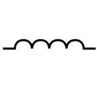 |
Inductor schematic symbol (general) | Coil / solenoid that generates magnetic field. |
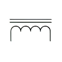 |
Iron core inductor symbol | The iron core inductor is made by surrounding an iron core with a coil of insulated copper wire, which serves as the conductive material. |
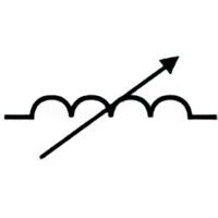 |
Variable inductor symbol | This particular kind of inductor possesses adjustable inductance, which can be altered while the circuit is in operation, as commonly observed in radio systems. |
| → Electric contacts symbols ← | ||
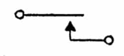 |
Form A contacts | MAKE or SPST-NO (Form A contacts, normally open). |
 |
Form B contacts | BREAK or SPST-NC (Form B contacts, normally closed). |
| Form C contacts | BREAK, MAKE (TRANSFER). | |
| → Adjustability and variability ← | ||
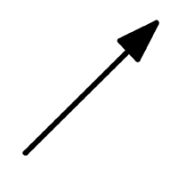 |
Adjustability, general symbol | Adjustability” pertains to a quantity associated with a device represented by the symbol, the value of which may be set or controlled by external means. |
 |
Adjustability, non-linear | |
 |
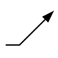
Linear variability, general symbol. | “Variability” pertains to a quantity associated with a device represented by the symbol, the value of which is dependent on factors internal to the device. |
| → Physical State Symbols ← | ||
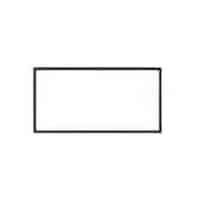 |
Material, unspecified | |
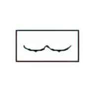 |
Material, liquid | Physical State of Matter. |
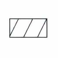 |
Material, solid | Physical State of Matter. |
| → Polarity Symbols ← | ||
 |
Plus; positive polarity | In the realm of electrical apparatus that either operates on or produces unidirectional electrical flow, the objective is to discern the terminal(s) endowed with positive polarity. |
 |
Minus; negative polarity | In the context of machinery designed for employing or producing direct current, the task at hand is to pinpoint the terminal(s) associated with negative polarity. |
| → AC and DC Symbols ← | ||
 |
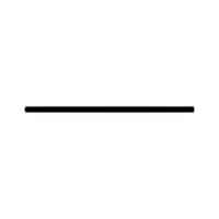
Direct current | To indicate on the rating plate that the equipment is suitable for direct current only; to identify relevant terminals. |
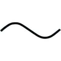 |
Alternating current | To indicate on the rating plate that the equipment is suitable for alternating current only; to identify relevant terminals. |
| → Wire Symbols ← | ||
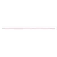 |
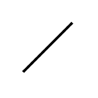
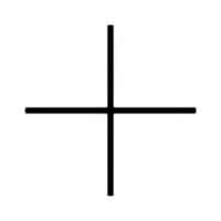
Electric line / cable / Wire | Connection, general symbol. |
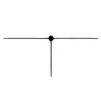 |
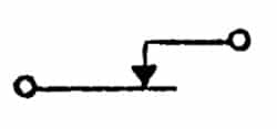
T-connection | Shown with junction symbol. |
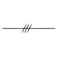 |
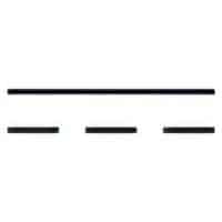
Group of connections symbol | Three connections shown. |
Table of electrical symbols