Before writing this article, I thoroughly researched the relevant regulatory documentation regarding switch and push button symbols. In this article, I will provide descriptions and graphical representations of common switch and push button symbols as specified by key standards organizations such as IEC and IEEE / ANSI. We’ll explore symbols for various switch configurations like single-pole, multi-position, passing, early/late operation, and mechanically delayed. Push button symbols for manual and emergency stop switches are also covered.
Download switch and push button symbols in JPG ►
See also: electric contacts symbols ►
| Symbol | Description | Notes |
|---|---|---|
 |
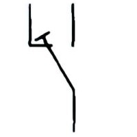
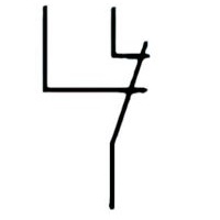
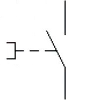
Name: Limit switch, general
Source: IEC 60417-2020 |
– |
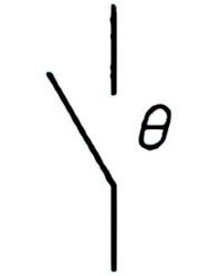 |
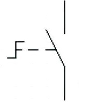
Name: Temperature sensitive switch, make contact
Source: IEC 60617-2019, ANSI/IEEE Std 315A-1986 |
A1 |
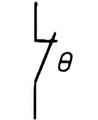 |
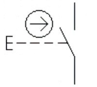
Name: Temperature sensitive switch, break contact
Source: IEC 60617-2019, ANSI/IEEE Std 315A-1986 |
– |
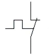 |
Name: Thermal switch, self-operating, break contact
Alternative name: Bimetal break contact Remark: It is important to distinguish between a contact as shown and a contact of a thermal relay. Source: IEC 60617-2019, ANSI/IEEE Std 315A-1986 |
– |
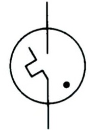 |
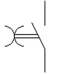
Name: Gas discharge tube with thermal element
Alternative name: Starter for fluorescent lamp Source: IEC 60617-2019, ANSI/IEEE Std 315A-1986 |
– |
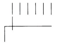 |
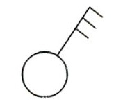
Name: Multi-position switch
Remark: Six positions shown Source: IEC 60617-2019, ANSI/IEEE Std 315A-1986 |
– |
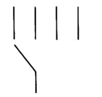 |
Name: Multi-position switch, maximum four positions
Source: IEC 60617-2019, ANSI/IEEE Std 315A-1986 |
– |
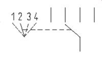 |
Name: Multi-position switch, with position diagram
Source: IEC 60617-2019, ANSI/IEEE Std 315A-1986 |
A2 |
 |
Name: Switch-disconnector; On-load isolating switch
Source: IEC 60617-2019, ANSI/IEEE Std 315A-1986 |
– |
 |
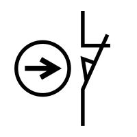
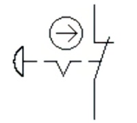
Name: Switch-disconnector, automatic release; On-load isolating switch, automatic release
Remark: With automatic tripping initiated by a built-in measuring relay or release. Source: IEC 60617-2019, ANSI/IEEE Std 315A-1986 |
– |
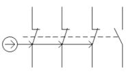 |
Name: Switch with positive opening
Remark: Switch with positive opening operation of the three main break contacts and the auxiliary make contact without positive operation. Source: IEC 60617-2019, ANSI/IEEE Std 315A-1986 |
– |
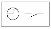 |
Name: Time switch
Source: IEC 60617-2019, ANSI/IEEE Std 315A-1986 |
– |
 |
Name: Foot switch
Alternative name: push button operated by foot Source: IEC 60617-2019, IEEE Std 315-1993 |
A3 |
 |
Name: Double two-way single pole switch
Source: IEC 60617-2019 |
– |
 |
Name: Combi-switch: two-way single pole and single pole on-off switch
Source: IEC 60617-2019 |
– |
 |
Name: Combi-switch: two-way single pole switch with dimmer
Source: IEC 60617-2019 |
– |
 |
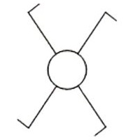
Name: Three pole switch
Alternative name: Three phase switch Source: IEC 60617-2019 |
A4, A5 |
 |
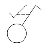
Name: Pull-cord single pole switch
Source: IEC 60617-2019 |
A4, A6 |
Table 1 – Symbols of switches
| Symbol | Description | Notes |
|---|---|---|
 |
Name: Make contact, general symbol; Switch, general symbol. Form 1.
Source: IEC 60617-2019, ANSI/IEEE Std 315A-1986 |
– |
 |
Name: Make contact, general symbol; Switch, general symbol. Form 2.
Source: IEC 60617-2019, ANSI/IEEE Std 315A-1986 |
– |
 |
Name: Break contact
Source: IEC 60617-2019, ANSI/IEEE Std 315A-1986 |
– |
 |
Name: Change-over break before make contact
Source: IEC 60617-2019, ANSI/IEEE Std 315A-1986 |
– |
 |
Name: Change-over make before break contact, both ways. Form 1.
Source: IEC 60617-2019, ANSI/IEEE Std 315A-1986 |
– |
 |
Name: Change-over make before break contact, both ways. Form 2.
Source: IEC 60617-2019, ANSI/IEEE Std 315A-1986 |
– |
 |
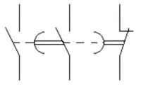
Name: Change-over contact with off-position
Source: IEC 60617-2019, ANSI/IEEE Std 315A-1986 |
– |
 |
Name: Contact with two makes
Source: IEC 60617-2019, ANSI/IEEE Std 315A-1986 |
– |
 |
Name: Contact with two breaks
Source: IEC 60617-2019, ANSI/IEEE Std 315A-1986 |
– |
Table 2 – Symbols of switches of two and three positions
| Symbol | Description | Notes |
|---|---|---|
 |
Name: Passing make contact when actuated
Remark: The contact is closing momentarily when its operating device is actuated. Source: IEC 60617-2019, ANSI/IEEE Std 315A-1986 |
– |
 |
Name: Passing make contact when released
Remark: The contact is closing momentarily when its operating device is released. Source: IEC 60617-2019, ANSI/IEEE Std 315A-1986 |
– |
 |
Name: Passing make contact
Remark: The contact is closing momentarily when its operating device is actuated or released. Source: IEC 60617-2019, ANSI/IEEE Std 315A-1986 |
– |
Table 3 – Symbols of switches of step in two-position
| Symbol | Description | Notes |
|---|---|---|
 |
Name: Make contact, early closing
Remark: The contact is early to close relative to the other make contacts of a contact assembly. Source: IEC 60617-2019, ANSI/IEEE Std 315A-1986 |
– |
 |
Name: Make contact, late closing
Remark: The contact is late to close relative to the other make contacts of a contact assembly. Source: IEC 60617-2019, ANSI/IEEE Std 315A-1986 |
– |
 |
Name: Break contact, late opening
Remark: The contact is late to open relative to the other break contacts of a contact assembly. Source: IEC 60617-2019, ANSI/IEEE Std 315A-1986 |
– |
 |
Name: Break contact, early opening
Remark: The contact which is early to open relative to the other break contacts of a contact assembly. Source: IEC 60617-2019, ANSI/IEEE Std 315A-1986 |
– |
Table 4 – Early and late operating switches
| Symbol | Description | Notes |
|---|---|---|
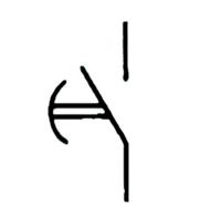 |
Name: Make contact, delayed closing
Remark: The closing of the contact is delayed when the device containing the contact is being activated. Source: IEC 60617-2019, ANSI/IEEE Std 315A-1986 |
A7 |
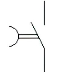 |
Name: Make contact, delayed opening
Remark: The opening of the contact is delayed when the device containing the contact is being de-activated. Source: IEC 60617-2019, ANSI/IEEE Std 315A-1986 |
A7 |
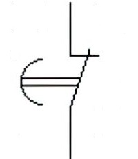 |
Name: Break contact, delayed opening
Remark: The opening of the contact is delayed when the device containing the contact is being activated. Source: IEC 60617-2019, ANSI/IEEE Std 315A-1986 |
A7 |
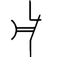 |
Name: Break contact, delayed closing
Remark: The closing of the contact is delayed when the device containing the contact is being de-activated. Source: IEC 60617-2019, ANSI/IEEE Std 315A-1986 |
A7 |
 |
Name: Make contact, delayed
Remark: The contact is delayed both when the device containing the contact is being activated and when it is being de-activated. Source: IEC 60617-2019, ANSI/IEEE Std 315A-1986 |
A7 |
 |
Name: Contact assembly
Remark: The contact assembly is shown with one make contact not delayed, one make contact delayed when the device containing the contact is being activated and one break contact delayed when the device containing the contact is being de-activated. Source: IEC 60617-2019, ANSI/IEEE Std 315A-1986 |
A7 |
Table 5 – Symbols of switches with intentional delay
| Symbol | Description | Notes |
|---|---|---|
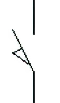 |
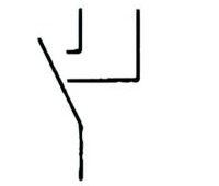
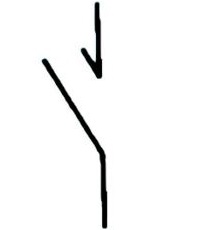
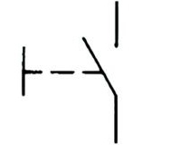
Name: Position switch, make contact
Source: IEC 60617-2019 |
A8 |
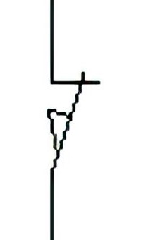 |
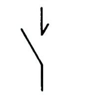
Name: Position switch, break contact
Source: IEC 60617-2019 |
A8 |
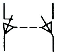 |
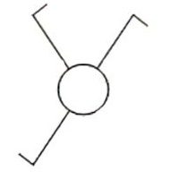
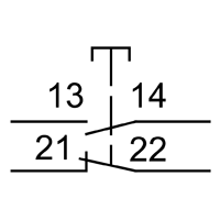
Name: Position switch assembly
Remark: Mechanically operated in both directions with two separate circuits Source: IEC 60617-2019, ANSI/IEEE Std 315A-1986 |
A8 |
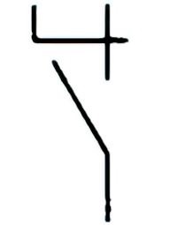
 |
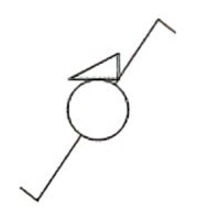
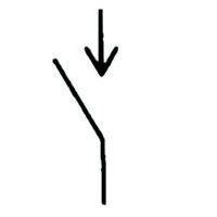
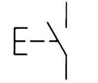
Name: Position switch, break contact, positive operation
Alternative name: Limit switch Source: IEC 60617-2019, ANSI/IEEE Std 315A-1986 |
A8 |
Table 6 – Symbols of position switches
| Symbol | Description | Notes |
|---|---|---|
 |
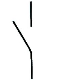
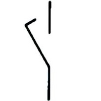
Name: Switch, manually operated, general symbol
Source: IEC 60617-2019, ANSI/IEEE Std 315A-1986 |
A9, A10 |
 |
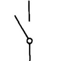
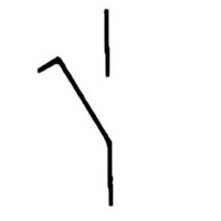
Name: Switch, manually operated, push-button, automatic return
Source: IEC 60617-2019, ANSI/IEEE Std 315A-1986 |
A9 |
 |
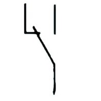
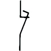
Name: Switch, manually operated, pulling, automatic return
Source: IEC 60617-2019, ANSI/IEEE Std 315A-1986 |
A9 |
 |
Name: Switch, manually operated, turning, stay-put
Source: IEC 60617-2019, ANSI/IEEE Std 315A-1986 |
A10 |
 |
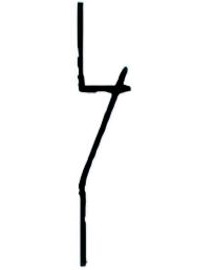
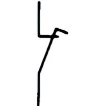
Name: Switch, manually operated with positive operation, push-button, automatic return
Source: IEC 60617-2019, ANSI/IEEE Std 315A-1986 |
A9 |
 |
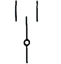
Name: Control switch operated by pushing
Source: IEC 60417-2019 |
– |
 |
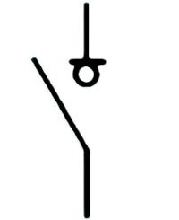
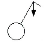
Name: Switch, emergency stop
Remark: “Mushroom-head” activated, with positive opening operation of the break contact and maintain position. Source: IEC 60417-2019 |
A9 |
Table 7 – Symbols of push-button switches
A1:
The letter THETA may be replaced by the operating temperature conditions.
A2:
It is sometimes convenient to indicate the purpose of each switch position by adding text to the position diagram. It is also possible to indicate limitations of movement of the operating device.
A3:
Graphical symbol , for use in installation diagrams, represents a device (switch) which has a single actuator. See circuit diagram presentation of symbol :
A4:
The mounting methods and/or directions of a device may be specified by the addition of letter codes adjacent to the symbol. IEC 61082-1 (clause 8.3) specifies the following letters:
- H = Horizontal (components mounted side by side)
- V = Vertical
- F = Flush (recessed)
- S = Surface
- B = Floor (bottom)
- T = Ceiling (top)
For the mounting in hidden locations, which may be of relevance for detectors, additional letters may be specified. Such letters shall be explained in the document or in supporting documentation.
A5:
Graphical symbol , for use in installation diagrams, represents a device (switch) which has one actuator for three contacts. See circuit diagram presentation of symbol : 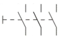
A6:
Graphical symbol , for use in installation diagrams, represents a device (switch) which has a single actuator. See circuit diagram presentation of symbol :
A7:
See symbols 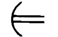 and
and 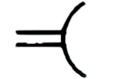 . Closing and opening of the contact is delayed with respect to the activation or deactivation operation. The movement is delayed in the direction towards the centre of the arc (“parachute effect”). The symbol for delayed action may be drawn on that side of the contact symbol which is most suitable for the application and for the placing of item designations.
A8:
Where in a set of contacts one or some of them are constructed to have positive opening operation this positivity may concern:
- either the opening of break contact(s) (for example : Position switch and : Emergency stop switch) or the closing of a make contact (for example : Alarm) and
- either all the contacts or only particular contacts (see for example ) but
- not both the opening and the closing of the same contact.
A9:
Devices with “push” or “pull” operation most often have automatic return. It is therefore not necessary to show the automatic return symbol 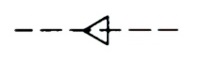 . On the other hand, a detent symbol
 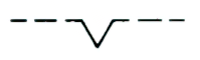 shall be shown in those cases where non-return exists.
A10:
Devices operated by turning do not usually have automatic return. It is therefore not necessary for the detent symbol to be shown. On the other hand, the automatic return symbol should be shown in those cases where an automatic return exists.