Protection against electric shock is a provision of measures reducing the risk of electric shock [definition based on IEC 60050-195-2021].
Protective provision is a independent provision intended to protect against electric shock under specified conditions.
IEC 61140-2016
Note 1 to entry: The provision may be a means or technique or device or process.
Enhanced protective provision is a protective provision having a reliability of protection not less than that provided by two independent protective provisions.
IEC 61140-2016
Protective measure is an appropriate combination of protective provisions for protection against electric shock.
IEC 61140-2016
The fundamental rule of protection against electric shock is:
- live parts, such as energized conductors, must not be accessible, and
- conductive parts which are accessible, such as metal enclosures of equipment or metal pipes, must not be hazardous-live.
These two conditions must be achieved both in normal conditions (no faults on the electrical system) and under single fault conditions (such as a fault from a live conductor to a metal casing).
An electrical burn is a burning of the skin or an organ caused by an electric current along its surface or through it.
See the article: https://www.asutpp.com/electrical-burn.html
Protection against electric shock shall be provided by basic protection provision (against direct contact) and by fault protection provision (against indirect contact). Alternatively, protection against electric shock is provided by an enhanced protective provision, which provides protection under normal conditions and under single-fault conditions.
Basic protection shall consist of one or more provisions that, under normal conditions, prevent contact with hazardous-live-parts.
NOTE. Paints, varnishes, lacquers and similar products alone are generally not considered to provide adequate insulation for protection against electric shock in normal service.
Where solid basic insulation is used, it shall prevent contact with hazardous-live-parts.
In case of high-voltage installations and equipment, a voltage may be present on the surface of solid insulation and further precautions shall be considered.
 Figure 1. Protection by the insulation of live parts
Where basic insulation is provided by air, access to hazardous-live-parts or entering the danger zone shall be prevented by obstacles, protective barriers or enclosures as specified in subclause “Protective Barriers or Enclosures” and “Obstacles” or by placing out of arm’s reach as specified in subclause “Placing Out of Arm’s Reach”.
Protective barriers or enclosures shall prevent:
- in the case of low-voltage installations and equipment, access to hazardous-live-parts by providing a degree of protection against electric shock of at least IPXXB or IP2X of IEC 60529 and, for readily accessible horizontal top surfaces of protective barriers or enclosures, at least IPXXD or IP4X;
- in the case of high-voltage installations and equipment, entering the danger zone by providing a degree of protection of at least IPXXB or IP2X of IEC 60529, and consideration shall be given to providing a degree of protection of at least IPXXD or IP4X for readily accessible horizontal top surfaces of protective barriers or enclosures.
NOTE. The IP code applies to the enclosures of electrical equipment of rated voltage not exceeding 72,5 kV.
 Figure 2. Example of isolation by enclosure
Protective barriers or enclosures shall have sufficient mechanical strength, stability and durability to maintain the specified degree of protection, taking account of all relevant influences from the environment and from inside the enclosure. They shall be firmly secured in place.
Where the design or construction allows for the removal of protective barriers, the opening of enclosures or the removal of parts of enclosures, access to hazardous-live-parts or entering the danger zone shall be possible only:
- by the use of a key or tool, or
- after isolation of hazardous-live-parts from the supply circuit where the enclosure would no longer provide protection, restoration of the supply shall become possible only after replacement of protective barriers or parts of enclosures or after the closing of doors, or
- where an intermediate barrier still maintains the required degree of protection, such barrier being removable only by the use of a key or tool.
Obstacles are intended to protect skilled or instructed persons but their use is not permitted for the protection of ordinary persons.
During the operation of the installation, system or equipment under special operating and servicing conditions, obstacles shall prevent:
- in the case of low-voltage installations and equipment, unintentional contact with hazardous-live-parts, or
- in the case of high-voltage installations and equipment, unintentional entering the danger zone.
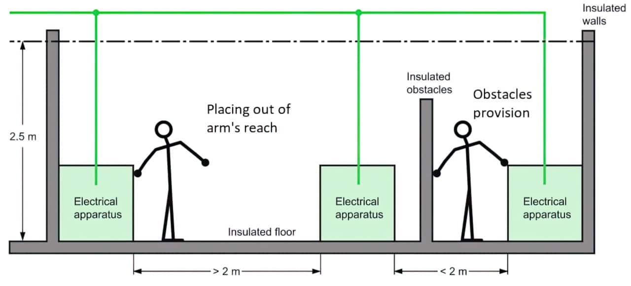 Figure 3. Placing out of arm’s reach and obstacles provision
Obstacles may be removable without using a key or tool but shall be so secured as to make unintentional removal unlikely.
Where a conductive obstacle is separated from hazardous-live-parts by basic insulation only, it is considered to be an exposed-conductive-part, and measures for fault protection shall also be applied.
Where provisions specified in subclauses “Basic Insulation”, “Protective Barriers or Enclosures”, “Obstacles”, “Limitation of Voltage” and “Limitation of Steady-State Touch Current and Energy” are found to be not applicable, placing out of arm’s reach (see figure 3) may be appropriate to prevent:
- in the case of low-voltage installations and equipment, unintentional simultaneous access to conductive parts between which a hazardous voltage can exist,
- in the case of high-voltage installations and equipment, unintentional entering into the danger zone.
Details shall be specified by technical committees.
For low-voltage installations, parts that are separated by a distance of more than 2,5 m are normally considered not to be simultaneously accessible. Where access is restricted to skilled or instructed persons, reduced distances may be specified.
Where a distance is expected to be reduced by objects which a person uses or holds in the hand, such as a tool or a ladder, technical committees shall specify relevant restrictions, or an appropriate distance between conductive parts between which a hazardous voltage can exist.
NOTE. Two parts are deemed to be simultaneously accessible if they are not more than 2,50 m apart (see Figure 4).
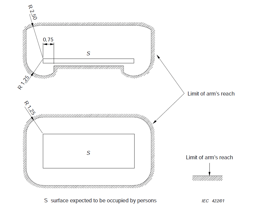 Figure 4. Zone of arm’s reach
Basic protection by the provision of limitation of voltage is fulfilled where both of the following conditions are fulfilled:
a) touch voltage under no circumstances exceeds:
1) 25 V a.c. r.m.s. or 60 V ripple-free d.c., when the equipment is normally used in dry locations only and large-area contact of live parts with the human body is not to be expected;
2) 6 V a.c. r.m.s. or 15 V ripple-free d.c. in all other cases;
b) the safety level is equivalent to that for SELV or PELV and supplied by one of the following sources:
1) a safety isolating transformer;
NOTE. Safety isolating transformers are those that comply with IEC 61558-2-6.
2) a source of current providing a degree of safety equivalent to that of a safety isolating transformer (e.g. motor generator);
3) electrochemical (e. g. battery).
It shall be acknowledged that the precise value of this voltage limit depends on a great number of influencing factors (such as environmental conditions, contact area).
Limitation of steady-state touch current and energy is a provision whereby touch currents or energy is limited to non-dangerous values.
It shall prevent persons or livestock from being subjected to values of steady-state touch current and energy liable to be above the values given in Clause 5 of IEC 61140-2016.
a) For touch current, the following values are proposed:
- a steady-state current flowing between simultaneously accessible conductive parts not exceeding the threshold of perception, 0,5 mA a.c. or 2 mA d.c. under normal operating conditions;
- values not exceeding the threshold of pain 3,5 mA a.c. or 10 mA d.c. may be specified under abnormal or fault conditions.
b) For stored energy available between simultaneously accessible conductive parts, the following values are proposed according to Figure 19 of IEC TS 60479-2:2007:
- 0,5 mJ corresponding to the threshold of pain; and
- 5 μJ corresponding to the threshold of perception.
Values for other frequencies, for other waveforms and for a.c. with superimposed d.c. are properly considered when measured with the appropriate IEC 60990 filtered touch current circuit.
NOTE. Medical electrical equipment within the scope of the IEC 60601 series can necessitate other levels.
In the case of high-voltage installations and equipment, potential grading shall prevent persons or livestock from hazardous step and touch voltages under normal conditions by providing a potential grading earth electrode.
NOTE. Potential grading is typically used for electrical railway systems and substations, where high earth currents occur.
Fault protection shall consist of one or more provision(s) independent of and additional to those for basic protection.
Supplementary insulation is a provision whereby fault protection is provided by insulation in addition to basic insulation
Supplementary insulation shall be dimensioned to withstand the same stresses as specified for basic insulation.
Protective-equipotential-bonding is a provision whereby items are bonded together to avoid hazardous touch voltages.
More information here: What Is an Equipotential Bonding? Definition, Meaning, Requirements, Examples
Protective screening shall consist of a conductive screen interposed between hazardous-live-parts of an installation, system or equipment and the part being protected. The protective screen:
- shall be connected to the protective-equipotential-bonding system of the installation, system or equipment and that interconnection shall comply with the requirements of subclause “Protective-Equipotential-Bonding”, and
- shall itself comply with the requirements for elements of protective-equipotential-bonding system.
A device shall be provided which indicates a fault. Depending on the method of neutral earthing, the fault current shall be disconnected either manually or automatically (see subclause “Automatic disconnection of supply”). The permissible value of the touch voltage depending on the fault duration shall be specified by technical committees based on IEC TS 60479-1.
For automatic disconnection of supply:
- a protective-equipotential-bonding system shall be provided, and
- a protective device operated by the fault current shall disconnect the line conductor(s) supplying the equipment, system or installation, in the event of a fault of negligible impedance between a line conductor and an exposed-conductive-part or a protective conductor in the circuit or equipment.
The protective device shall interrupt the fault current within a time specified by technical committees based on the IEC 60479 series. For low-voltage installations, the time to be specified depends on the prospective touch voltage produced across the protective-equipotential-bonding.
For steady-state fault currents which, with regard to protection against electric shock, need not lead to disconnection, a conventional touch voltage limit UL may be specified.
The protective device may be provided in any suitable upstream part of the installation, system or equipment, preferably at the origin of the circuit to be protected, and shall be selected taking into account the characteristics of the supply and the load, and of the impedance of the fault current loop.
Simple separation between a circuit and other circuits or earth shall be achieved by basic insulation throughout, rated for the highest voltage present.
A component connected between the separated circuits shall withstand the electric stresses specified for the insulation which it bridges and its impedance shall limit the prospective current flow through the component to the steady-state touch current values indicated in subclause “Limitation of steady-state touch current and energy”.
The environment shall have an impedance to earth of at least:
- 50 kΩ if the nominal system voltage does not exceed 500 V a.c. or d.c.;
- 100 kΩ if the nominal system voltage is above 500 V a.c. or d.c. and does not exceed 1 000 V a.c. or 1 500 V d.c.
NOTE 1. Methods for measuring the resistance of insulating floors and walls are included in Annex A to IEC 60364-6:2006.
NOTE 2. Impedance values for HV are not considered because this protective measure is not used.
Potential grading may be used by installation of additional earth electrodes to reduce the touch voltage and step voltage which appear in the case of a fault.
NOTE. Earth electrodes are usually buried at a horizontal distance of 1 m from the equipment or any conductive part, at a depth of 0,5 m below ground level and are connected to the earthing arrangement.
An enhanced protective provision shall provide both basic and fault protection.
Arrangements shall be made so that the protection provided by an enhanced protective provision is unlikely to become degraded and so that a single fault is unlikely to occur.
Reinforced insulation shall be designed to be able to withstand electric, thermal, mechanical and environmental stresses with the same reliability of protection as provided by double insulation (basic insulation and supplementary insulation).
This requires design and test parameters more severe than those specified for basic insulation (see IEC 60664-1).
NOTE 1. As an example for low-voltage applications, dimensioning of reinforced insulation with regard to impulse voltage is, where the concept of overvoltage categories (see Clause 443 of IEC 60364-4-44:2007) applies, specified to comply with the requirements of the overvoltage category which is one category higher than that specified for basic insulation.
NOTE 2. Reinforced insulation is mainly used in low-voltage installations and equipment but the application is not excluded in high-voltage installations and equipment.
Protective separation between a circuit and other circuits shall be achieved by means of
- basic insulation and supplementary insulation, each rated for the highest voltage present, i.e. double insulation, or
- reinforced insulation rated for the highest voltage present, or
- protective screening with the protective screen being separated from each adjacent circuit by basic insulation rated for the adjacent circuit voltage, or
- a combination of these provisions.
If conductors of the separated circuit are contained together with conductors of other circuits in a multi-conductor cable or in another grouping of conductors, they shall be insulated, individually or collectively, for the highest voltage present, so that double insulation is achieved.
If any component is connected between the separated circuits, that component shall comply with the requirements for protective impedance devices.
A limited current source shall be so designed that it cannot supply touch currents in excess of the limit values indicated in subclause “Limitation of steady-state touch current and energy”.
The requirements of “Limitation of steady-state touch current and energy” apply also to any likely failure of a single component of the limited current source.
The limit values should be determined by the relevant technical committee.
A protective impedance device shall reliably limit the touch current to the values indicated in subclause “Limitation of steady-state touch current and energy”.
The protective impedance device shall withstand the electric stresses specified for the insulation which it bridges.
These requirements apply also to any likely failure of a single component of the protective impedance device.
In the case of low voltage, an RCD with IΔn ≤ 30 mA is applied as an additional protective provision where:
- a) basic protection is provided by one of the provisions of subclause “basic insulation” or subclause “protective barriers or enclosures”, and/or
- b) fault protection is provided by one of the provisions of subclause “protective-equipotential-bonding” and subclause “automatic disconnection of supply”.
This protective provision is recognized as additional protection in the event of failure of the provision for basic protection and/or the provision for fault protection, or carelessness by users.
Devices for additional protection shall disconnect the live conductors by providing an isolating distance.
Residual current monitoring devices (RCMs) are not considered to be protective devices.
Additional protection by supplementary equipotential bonding is a provision whereby dangerous touch voltages are avoided by bonding of items.
Supplementary equipotential bonding is provided as an additional protective provision where:
- a) basic protection is provided by one of the provisions of subclause “basic insulation” or subclause “protective barriers or enclosures”, and
- b) fault protection is provided by protective earthing, protective equipotential bonding and automatic disconnection in the event of a fault.
This protective provision will help avoid hazardous voltages between exposed-conductive-parts and extraneous-conductive-parts which can be touched simultaneously.
In each part of an installation one or more protective measures shall be applied, taking account of the conditions of external influence.
The following protective measures generally are permitted:
The protective measures applied in the installation shall be considered in the selection and erection of equipment.
In electrical installations the most commonly used protective measure is automatic disconnection of supply.
- IEC 60050-195-2021
- IEC 61140-2016
- IEC 60364-4-41:2017