After a detailed analysis of the existing normative documentation (IEC and IEEE / ANSI), I have compiled a complete list of currently valid relay symbols.
Relay symbols play a critical role in understanding and implementing electrical systems, yet their intricacies can be challenging to navigate for professionals and non-professionals alike. This article aims to provide electricians, engineers, technicians, and curious homeowners with a helpful overview of common relay symbols, enabling clearer communication and safer electrical work. We’ll explore symbols for various relay types—all-or-nothing, measuring, and static—looking at general forms as well as application-specific variants. Diagrams and descriptions define each symbol, explaining the mechanics relayed and noting relevant standards.
Download relay symbols in JPG ►
See also: choke / coil / inductor symbols ►
| Symbol | Description | Notes |
|---|---|---|
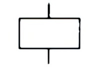 |
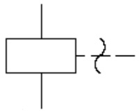
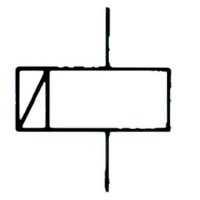
Name: Operating device, general symbol; Relay coil, general symbol. Form 1.
Source: IEC 60617-2019, ANSI/IEEE Std 315A-1986 |
A1 |
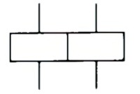 |
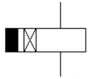
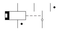
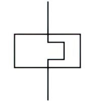
Name: Operating device; Relay coil. Form 1.
Remark: Shown with two separate windings Source: IEC 60617-2019, ANSI/IEEE Std 315A-1986 |
– |
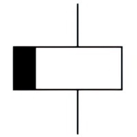 |
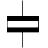
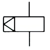
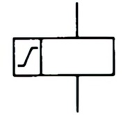
Name: Relay coil of a slow-releasing relay
Source: IEC 60617-2019, ANSI/IEEE Std 315A-1986 |
– |
 |
Name: Relay coil of a slow-operating relay
Source: IEC 60617-2019, ANSI/IEEE Std 315A-1986 |
– |
 |
Name: Relay coil of a slow-operating and slow-releasing relay
Source: IEC 60617-2019, ANSI/IEEE Std 315A-1986 |
– |
 |
Name: Relay coil of a high speed relay
Remark: Fast-operating and fast-releasing Source: IEC 60617-2019, ANSI/IEEE Std 315A-1986 |
– |
 |
Name: Relay coil of a relay unaffected by alternating current
Source: IEC 60617-2019, ANSI/IEEE Std 315A-1986 |
– |
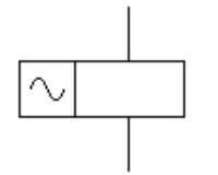 |
Name: Relay coil of an alternating current relay
Source: IEC 60617-2019, ANSI/IEEE Std 315A-1986 |
– |
 |
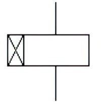
Name: Relay coil of a mechanically resonant relay
Source: IEC 60617-2019, ANSI/IEEE Std 315A-1986 |
– |
 |
Name: Relay coil of a mechanically latched relay
Source: IEC 60617-2019, ANSI/IEEE Std 315A-1986 |
– |
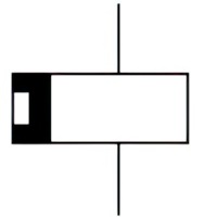 |
Name: Relay coil of a polarized relay
Source: IEC 60617-2019, ANSI/IEEE Std 315A-1986 |
A2 |
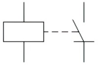
 |
Name: Polarized relay, self restoring
Remark: Self restoring, operating for only one direction of current in the winding Source: IEC 60617-2019, ANSI/IEEE Std 315A-1986 |
– |
 |
Name: Polarized relay with neutral position
Remark: With neutral position, self restoring, operating for either direction of current in the winding. Source: IEC 60617-2019, ANSI/IEEE Std 315A-1986 |
– |
 |
Name: Polarized relay, stable positions
Remark: Shown with two stable positions. Source: IEC 60617-2019, ANSI/IEEE Std 315A-1986 |
– |
 |
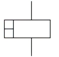
Name: Relay coil of a remanent relay. Form 1.
Source: IEC 60617-2019, ANSI/IEEE Std 315A-1986 |
– |
 |
Name: Relay coil of a remanent relay. Form 2.
Source: IEC 60617-2019, ANSI/IEEE Std 315A-1986 |
– |
 |
Name: Operating device of a thermal relay
Source: IEC 60617-2019 |
– |
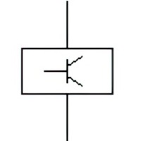 |
Name: Operating device of an electronic relay
Source: IEC 60617-2019 |
– |
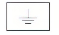 |
Name: Ground relay, Earth fault relay
Remark: Relay which operates when a failure of insulation to earth is detected in the equipment or circuits protected. Source: IEC TR 62711-2011 |
– |
Symbols of relays
| Symbol | Description | Notes |
|---|---|---|
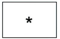 |
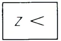
Name: Measuring relay; Device related to a measuring relay
Source: IEC 60617-2019, ANSI/IEEE Std 315A-1986 |
A3, A4, A5, A6, A7 |
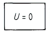 |
Name: No voltage relay
Source: IEC 60617-2019, ANSI/IEEE Std 315A-1986 |
– |
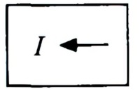 |
Name: Reverse current relay
Source: IEC 60617-2019, ANSI/IEEE Std 315A-1986 |
– |
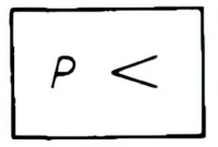 |
Name: Underpower relay
Source: IEC 60617-2019, ANSI/IEEE Std 315A-1986 |
– |
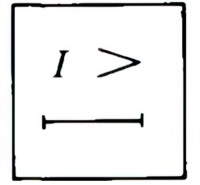 |
Name: Delayed overcurrent relay
Source: IEC 60617-2019, ANSI/IEEE Std 315A-1986 |
– |
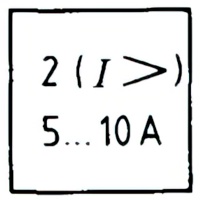 |
Name: Overcurrent relay
Remark: Shown with two measuring elements and a setting range from 5 A to 10 A. Source: IEC 60617-2019, ANSI/IEEE Std 315A-1986 |
– |
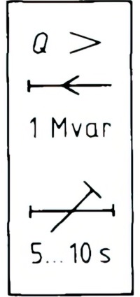 |
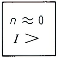
Name: Overpower relay for reactive power
Remark: Overpower relay for reactive power: – energy-flow towards the busbars operating value 1 Mvar time-lag adjustable from 5 s to 10 s Source: IEC 60617-2019, ANSI/IEEE Std 315A-1986 |
– |
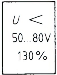 |
Name: Undervoltage relay
Remark: Undervoltage relay shown with: – setting range from 50 V to 80 V resetting ratio 130% Source: IEC 60617-2019, ANSI/IEEE Std 315A-1986 |
– |
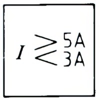 |
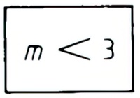
Name: Current relay
Remark: With maximum and minimum settings, shown with limits 3 A and 5 A. Source: IEC 60617-2019, ANSI/IEEE Std 315A-1986 |
– |
 |
Name: Under-impedance relay
Source: IEC 60617-2019, ANSI/IEEE Std 315A-1986 |
– |
|
Name: Relay detecting short-circuits between windings
Source: IEC 60617-2019, ANSI/IEEE Std 315A-1986 |
– |
 |
Name: Divided-conductor detection relay
Source: IEC 60617-2019, ANSI/IEEE Std 315A-1986 |
– |
 |
Name: Phase-failure detection relay
Remark: Shown for a three-phase system. Source: IEC 60617-2019, ANSI/IEEE Std 315A-1986 |
– |
 |
Name: Locked-rotor detection relay
Remark: Operating by current measuring. Source: IEC 60617-2019, ANSI/IEEE Std 315A-1986 |
– |
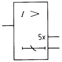 |
Name: Overcurrent relay
Remark: With two outputs, one is active when the current is above five times the setting value, the other is active depending on the inverse time-lag characteristic setting of the device. Source: IEC 60617-2019, ANSI/IEEE Std 315A-1986 |
– |
 |
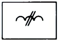
Name: Buchholz protective device; Gas relay
Source: IEC 60617-2019, ANSI/IEEE Std 315A-1986 |
– |
 |
Name: Device for auto-reclosing; Auto-reclose relay
Source: IEC 60617-2019, ANSI/IEEE Std 315A-1986 |
– |
| Symbol | Description | Notes |
|---|---|---|
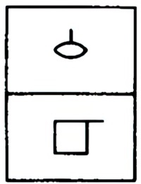
 |
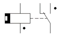
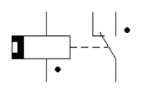
Name: Static relay, general symbol
Remark: Shown with semiconductor make contact. Source: IEC 60617-2019 |
A8 |
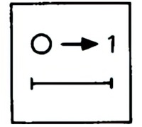
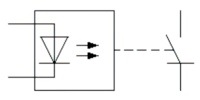 |
Name: Static relay
Remark: With light emitting diode as actuator shown with make contact semiconductor. Source: IEC 60617-2019 |
– |
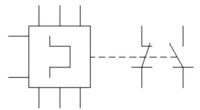 |
Name: Static thermal overload relay
Remark: Three-pole thermal overload relay with two semiconductor contacts one semiconductor make contact and one semiconductor break contact; the actuator needs a separate auxiliary power supply. Source: IEC 60617-2019 |
– |
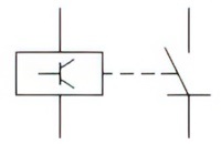 |
Name: Static relay
Remark: Semiconductor operating device with semiconductor make contact. Source: IEC 60617-2019 |
– |
Symbols of static relay
A1:
Operating devices with several windings may be indicated by inclusion inside the outline of the appropriate number of inclined strokes.
A2:
Polarity dots may be used to indicate the relationship between the direction of the current through the winding of a polarized relay and the movement of the contact arm according to the following connection.
When the winding terminal identified by the polarity dot is positive with respect to the other winding terminal, the contact arm moves or tends to move towards the position marked with the dot.
A3:
The asterisk shall be replaced by one or more letters or qualifying symbols indicating the parameters of the device, in the following order:
- characteristic quantity and its mode of variation;
- direction of energy flow;
- setting range;
- re-setting ratio;
- delayed action;
- value of time delay.
A4:
Letter symbols for characteristic quantities shall be in accordance with established standards, for example, IEC 60027 and ISO 31.
A5:
A figure giving the number of similar measuring elements may be included in the symbol as shown in example .
A6:
The symbol may be used as a functional symbol representing the whole of the device, or as a symbol representing only the actuating element of the device.
A7:
If appropriate symbols indicating the parameter of the device are not applicable, the asterisk may also be replaced by commonly accepted designations e.g. IEC TR 62711.
A8:
A qualifying symbol to denote the type of actuating element may be added.