Surge protective device (SPD) is a device that contains at least one nonlinear component that is intended to limit surge voltages and divert surge currents [Source: IEC 61643-11-2011].
NOTE – An SPD is a complete assembly, having appropriate connecting means.
The British Standard BS 7671 defined the term “surge protective device (SPD)” as follows:
Surge protective device (SPD) is a device that is intended to limit transient overvoltages and divert surge currents. It contains at least one non-linear component.
BS 7671:2018+A2:2022
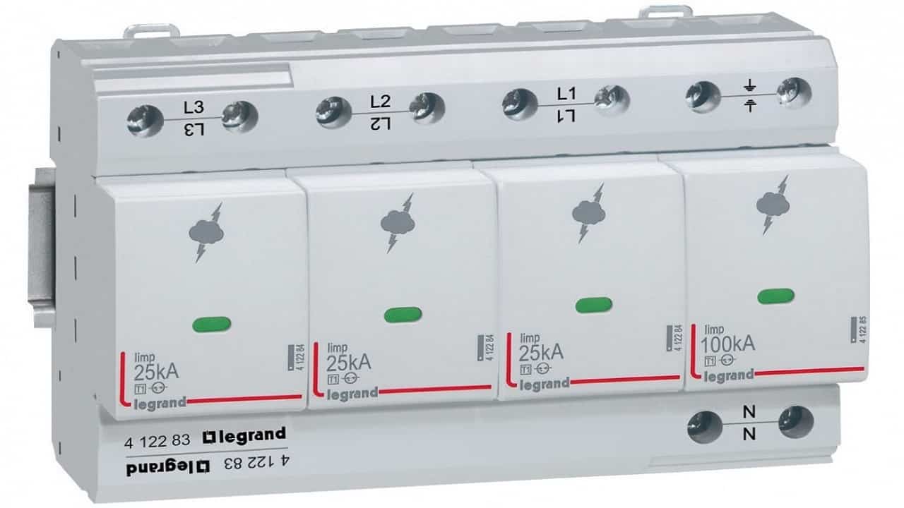 Figure 1 – Surge protective device (SPD) example
The working principle of SPDs is based on the use of metal oxide varistors (MOVs) or gas discharge tubes (GDTs) that divert the excess electrical energy away from the protected equipment.
When a surge occurs, the voltage across the MOV or GDT increases, causing it to conduct current and divert the excess energy to ground or to a neutral conductor. As a result, the voltage across the protected equipment is limited to a safe level, preventing damage to the equipment.
It is important to note that SPDs do not prevent surges from occurring; rather, they limit the voltage that reaches the equipment being protected. Additionally, SPDs should be installed by a qualified electrician and regularly inspected to ensure they are functioning properly.
Their functioning in power systems can be described as follows.
- In the absence of surges: the surge protective device shall not have a significant influence on the operational characteristics of the system to which it is applied.
- During the occurrence of surges: the SPD responds to surges by lowering its impedance and thus diverting surge current through it to limit the voltage (in most cases much lower than its protective level Up). The surges could initiate a power follow current through the SPD depending on the SPD design (SPD with power follow current).
- After the occurrence of surges: the SPD recovers to a high-impedance state after the surges and extinguishes any possible power follow current.
The characteristics of SPDs are intended to achieve the above functions under normal service conditions. Normal service conditions are specified by the frequency of the power-system voltage, load current, altitude (i.e. air pressure), humidity and ambient air temperature.
The manufacture shall classify the SPDs in accordance with the following parameters.
- One. One-port SPD is surge protective device having no intended series impedance. A one port SPD may have separate input and output connections.
- Two. Two-port SPD is surge protective device having a specific series impedance connected between separate input and output connections.
- Voltage switching. Voltage switching type SPD is SPD that has a high impedance when no surge is present, but can have a sudden change in impedance to a low value in response to a voltage surge. Common examples of components used in voltage switching type SPDs are spark gaps, gas tubes and thyristors. These are sometimes called “crowbar type” components.
- Voltage limiting. Voltage limiting type SPD is SPD that has a high impedance when no surge is present, but will reduce it continuously with increased surge current and voltage. Common examples of components used in voltage limiting type SPDs are varistors and avalanche breakdown diodes. These are sometimes called “clamping type” components.
- Combination. Combination type SPD is surge protective device that incorporates both, voltage switching components and voltage limiting components. The SPD may exhibit voltage switching, limiting or both.
Information required for class I, class II and class III tests is given in Table 1.
| Tests | Required information | Test procedures (see subclasses of IEC 61643-11-2011) |
| Class I | Iimp | 8.1.1; 8.1.2; 8.1.3 |
| Class II | In | 8.1.2; 8.1.3 |
| Class III | Uoc | 8.1.4; 8.1.4.1 |
Table 1 – Class I, II and III tests
Notes:
Class I tests are tests carried out with the impulse discharge current Iimp, with an 8/20 current impulse with a crest value equal to the crest value of Iimp, and with a 1,2/50 voltage impulse.
Class II tests are tests carried out with the nominal discharge current In, and the 1,2/50 voltage impulse.
Class III tests are tests carried out with the 1,2/50 voltage – 8/20 current combination wave generator.
- Indoor. SPDs intended for use in enclosures and/or inside buildings or shelters. SPDs installed in outdoor enclosures or shelters are considered for indoor use.
- Outdoor. SPDs intended for use without enclosures and outside of buildings or shelters (e.g. on low-voltage overhead lines).
By definition, outdoor means outside closed shelters. Hence, such SPDs are subjected to all external conditions. Indoor means inside closed shelters. Hence, such SPDs are subjected to indoor atmospheric conditions.
- Accessible. An surge protective device which can be fully or partly touched by an unskilled person, without the use of a tool to open any covers or enclosures, once installed.
- Inaccessible (out-of-reach). An surge protective device which cannot be touched by an unskilled person either due to being mounted out of reach (e.g. mounted on overhead lines) or due to being located within enclosures which can only be opened by using a tool, once installed.
Out-of-reach means no access to live parts without the use of tools or other equipment.
- Internal;
- External;
- Both (internal and external).
- Thermal;
- Leakage current;
- Overcurrent;
According to IP code of IEC 60529.
- Normal. Normal range: –5 °C to +40 °C. This range addresses surge protective devices for indoor use in weather-protected locations having neither temperature nor humidity control and corresponds to the characteristics of external influences code AB4 in IEC 60364-5-51.
- Extended. Extended range: –40 °C to +70 °C. This range addresses surge protective devices for outdoor use in non weather protected locations.
- Normal. Normal range: 5 % to 95 %. This range addresses SPDs for indoor use in weather-protected locations having neither temperature nor humidity control and corresponds to the characteristics of external influences code AB4 in IEC 60364-5-51.
- Extended. Extended range: 5 % to 100 %. This range addresses SPDs for outdoor use in non weather protected locations.
- AC between 47 Hz and 63 Hz;
- AC other than the range of 47 Hz to 63 Hz;
This may require additional and/or modified test procedures.
Multipole SPD is a type of surge protective device with more than one mode of protection, or a combination of electrically interconnected SPDs offered as a unit.
- open circuit (standard type SPD);
- short-circuit (short-circuiting type SPD).
International standard IEC 61643-11 defines the characteristics and tests for SPD connected to low-voltage distribution systems.
Preferred values means values which are often used in practice. Depending on real conditions lower and in some cases higher values may be needed.
Frequency range is from 47 Hz to 63 Hz AC.
Impulse discharge current for class I test (Iimp) is a crest value of a discharge current through the SPD with specified charge transfer Q and specified energy W/R in the specified time.
Preferred values of impulse discharge current Iimp for class I tests:
- Iimp — 1; 2; 5; 10; 12,5; 20 and 25 kA;
- Q — 0,5; 1; 2,5; 5; 6,25; 10 and 12,5 As;
- W/R — 0,25; 1,0; 6,25; 25; 39; 100 and 156 kJ/Ω.
NOTE. Specific energy for class I test (W/R) is energy dissipated by a unit resistance of 1 Ώ with the impulse discharge current Iimp. This is equal to the time integral of the square of the current (W/ R = ∫ i2d t ).
Nominal discharge current for class II test (In) is a crest value of the current through the SPD having a current waveshape of 8/20.
NOTE. 8/20 current impulse is a current impulse with a nominal virtual front time of 8 μs and a nominal time to half-value of 20 μs.
Preferred values of nominal discharge current for class II tests In: 0,05; 0,1; 0,25; 0,5; 1,0; 1,5; 2,0; 2,5; 3,0; 5,0; 10; 15 and 20 kA.
Open circuit voltage (Uoc) is an open circuit voltage of the combination wave generator at the point of connection of the device under test.
Preferred values of open-circuit voltage for class III tests Uoc: 0,1; 0,2; 0,5; 1; 2; 3; 4; 5; 6; 10 and 20 kV.
Voltage protection level (Up) is the maximum voltage to be expected at the SPD terminals due to an impulse stress with defined voltage steepness and an impulse stress with a discharge current with given amplitude and waveshape.
The voltage protection level is given by the manufacturer and may not be exceeded by:
- the measured limiting voltage, determined for front-of-wave sparkover (if applicable) and the measured limiting voltage, determined from the residual voltage measurements at amplitudes corresponding to In and/or Iimp respectively for test classes II and/or I;
- the measured limiting voltage at Uoc, determined for the combination wave for test class III.
Preferred values of voltage protection level Up: 0,08; 0,09; 0,10; 0,12; 0,15; 0,22; 0,33; 0,4; 0,5; 0,6; 0,7; 0,8; 0,9; 1,0; 1,2; 1,5; 1,8; 2,0; 2,5; 3,0; 4,0; 5,0; 6,0; 8,0 and 10 kV.
Maximum continuous operating voltage (Uc) is the maximum r.m.s. voltage, which may be continuously applied to the SPD’s mode of protection.
The UC value covered by this standard may exceed 1 000 V.
The voltage applied continuously between the terminals of the surge protective device (SPD) must not exceed its maximum continuous operating voltage UC.
Preferred values of r.m.s. maximum continuous operating voltage Uc: 45; 52; 63; 75; 85, 95; 110; 130; 150; 175; 220; 230; 240; 255: 260; 275; 280; 320; 335; 350; 385; 400; 420; 440; 460; 510; 530; 600; 635; 660; 690; 800; 900; 1 000; 1 500; 1 800 and 2 000 V.
Main Requirements
Protection against direct contact.
These requirements are valid for accessible SPDs where the maximum continuous operating voltage Uc is above 50 V r.m.s.
For protection against direct contact (inaccessibility of live parts), surge protective devices shall be designed in such a way that live parts cannot be touched when the SPD is installed for the intended use.
SPDs, except SPDs classified for mounting out-of-reach-only, shall be so designed that, when they are wired and mounted as for normal use, live parts are not accessible, even after removal of parts which can be removed without the use of a tool.
The connection between the earthing terminals and all accessible parts connected thereto shall be of low resistance.
Residual current IPE.
For all SPDs with a terminal for the protective conductor, the residual current IPE shall be measured when all SPD terminals are connected to a power supply at the reference test voltage (UREF) according to the manufacturer’s instructions.
Voltage protection level Up.
The measured limiting voltage of the surge protective devices shall not exceed the voltage protection level that is specified by the manufacturer.
Operating duty.
The surge protective device shall be capable of withstanding specified discharge currents during application of the maximum continuous operating voltage Uc without unacceptable changes in its characteristics.
Disconnectors.
The SPD shall have disconnectors (which can be either internal, external or both), except surge protective devices for connection N-PE in TN and/or TT systems only. Their operation shall be indicated by a corresponding status indicator.
Thermal protection.
SPDs shall be protected against overheating due to degradation or overstress. This test is not performed on surge protective devices containing only voltage switching components and/or ABD devices.
Short-circuit current behaviour.
An SPD shall fail without causing a hazardous condition or withstand the prospective short-circuit currents of the power system that may occur during an SPD failure.
Compliance is checked by the test in accordance with 8.3.5.3, 8.3.5.3.1 and 8.3.5.3.2 of IEC 61643-11-2011.
These tests are not performed on surge protective devices classified for outdoor use and for mounting out of reach and for SPDs for connection N-PE in TN and/or TT systems only.
Status indicators.
The manufacturer shall provide information about the function of the indicator and the actions to be taken after change of status indication.
A status indicator may be composed of two parts (one of which is not replaced on replacement of the surge protective device), linked by a coupling mechanism which can be mechanical, optical, audio, electromagnetic, etc. The part of the status indicator which is not replaced shall be capable of operating at least 50 times.
The action of the coupling mechanism which operates the non-replaced part of the status indicator may be simulated by means other than operation of the section within the replaced part of the surge protective device, e.g. a separate electromagnet or a spring.
Where there is an appropriate standard for the type of indication used, this shall be met by the non-replaced part of the status indicator, with the exception that the indicator need only be tested for 50 operations.
Insulation resistance.
The insulation resistance of the surge protective device shall be sufficient with respect to leakage currents and protection against direct contact.
Dielectric withstand.
The dielectric withstand of the surge protective device shall be sufficient with respect to insulation breakdown and protection against direct contact.
Mounting.
SPDs shall be provided with appropriate means for mounting that will ensure mechanical stability. Mechanical coding/interlock shall be provided to prevent incorrect combinations of plug-in SPD modules and sockets.
External connections.
Electrical connections shall be possible using one of the following means:
- screw terminals and bolted connections;
- screwless terminals;
- insulation piercing connections;
- flat quick connect terminations;
- flying leads;
- other equally effective means;
or
- standardised plugs and/or sockets.
Compliance is checked by visual inspection.
Terminals shall be fastened to the surge protective device in such a way that they will not work loose if the clamping screws or the lock nuts are tightened or loosened. A tool shall be required to loosen the clamping screws or the lock nuts.
- a) Terminals for external conductors shall be such that the conductors may be connected so as to ensure that the necessary contact pressure is maintained permanently. The terminals shall be readily accessible under the intended conditions of use.
- b) The means for clamping the conductors in the terminals shall not serve to fix any other component, although they may hold the terminals in place or prevent them from turning.
- c) Terminals shall have adequate mechanical strength.
- d) Terminals shall be so designed that they clamp the conductor without undue damage to the conductor.
- e) Terminals shall be so designed that they clamp the conductor reliably and between metal surfaces.
- f) Terminals shall be so designed or positioned that neither a rigid solid conductor nor a wire of a stranded conductor can slip out while the clamping screws or nuts are tightened.
Air clearances and creepage distances.
The surge protective device shall have sufficient air clearances and creepage distances.
Mechanical strength.
All parts of the surge protective device relating to the protection against direct contact shall have sufficient mechanical strength.
This clause presents hypothetical systems for domestic and industrial facilities in which SPDs are installed. This annex is intended to provide information about the selection of SPDs in limited situations to illustrate the application principles contained in this document. It is not intended to address the unique aspects of the conditions that exist in all facilities or systems.
MV network: overhead line 10 km.
LV (230/400 V) network: overhead line 1 000 m; underground cable 200 m.
Ground flash density (NG): 2 strikes/km2/year (see 5.2.2 of IEC 61643-12-2020).
Location of the structure to be protected: on a flat area.
Structure of the electric installation: installation protected by an RCD type S at the entrance (withstand 3 kA 8/20). The short-circuit current capability at the entrance of the installation is 3 kA. There is a main electrical board at the entrance of the house (ground floor) and one subsidiary electrical board on the first floor.
Resistance of the earthing arrangement of the structure to be protected: 50 Ω.
Earthing system of the LV network: TT system. One phase and neutral distributed.
Nature of devices to be protected: electronic washing machine, computer, alarm at the entrance, video tape recorder and TV set, etc.
Due to the risk analysis it is probable that there is some interest in using surge protective devices (high value of NG, overhead lines both on MV and LV side of the transformer, electronic devices, etc.).
Due to the overhead lines medium lightning currents are expected; nominal discharge current (In) ≥ 5 kA 8/20 per wire at the entrance.
At the entrance, an alarm is to be protected (sensitive equipment); Up ≤ 1,5 kV. This may be achieved by a one-port SPD tested by class II tests with Up = 1,5 kV.
At the entrance, the short-circuit current capability is 3 kA RMS; short-circuit withstand of the SPD ≥3 kA RMS. For this the manufacturer recommends use of a fuse or the short-circuit breaking characteristics of an RCD circuit-breaker (back-up protection). If an RCD type S circuit-breaker is used at the entrance, the continuity of service is not assured for incoming surges in excess of 3 kA 8/20.
No additional protection against indirect contact is needed due to the presence of the RCD. A thermal disconnector is incorporated in the SPD itself.
As it is a TT system and in order to avoid too high a stress between phase and neutral: it is recommended that an SPD having three modes of protection be used (phase to neutral, neutral to earth and phase to earth).
The other devices to be protected need only protection between phase and neutral as the earth is not connected to them, except the washing machine where the earth is present for safety purposes. In this case, protection between phase and earth and neutral and earth may be necessary.
NOTE. Additional protection may be necessary if the TV antenna is earthed.
As the distance between the surge protective device at the entrance and the other devices, especially on the first floor, is high (10 m and 20 m respectively), other surge protective devices are necessary close to the devices to be protected. One should be located close to the washing machine and another one close to the video tape recorder and TV set. Another one is connected at the first-floor electrical board but could be connected direct on the computer plug as well (distance is small between this panel and the computer).
The other SPDs should see a lower surge current. Also, In = 2 kA class II tests is sufficient. Up = 0,8 kV is then proposed in the manufacturer’s catalogue. The distance of 20 m is sufficient to provide decoupling between the surge protective device located at the entrance and the first-floor one. But the 10 m between the entrance surge protective device and the other ground-floor SPDs is not sufficient to provide adequate decoupling due to the low value of Up = 0,8 kV. It is then better to choose another surge protective device with Up = 1,5 kV, for example, for the other ground-floor surge protective devices.
For these surge protective devices, the short-circuit current at their location is low and the manufacturer has incorporated the necessary disconnectors (thermal and short-circuit). See Figure 2.
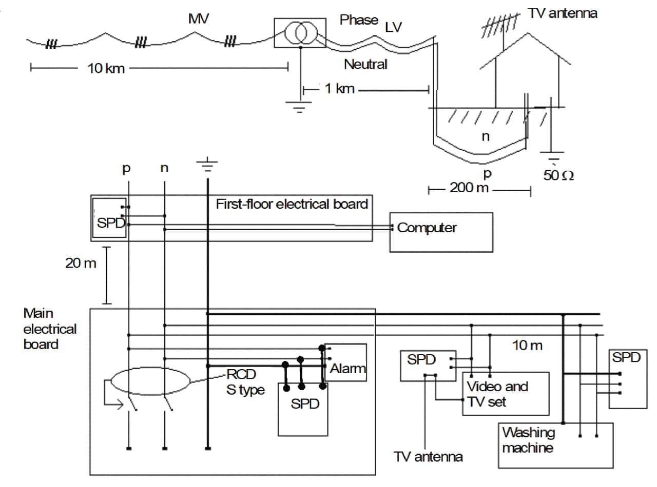 Figure 2 – Domestic installation
MV network: overhead line 10 km.
LV (230/400 V) network: underground cable 2 runs of 100 m.
NG = 0,5 strikes/km2/ year (see 5.2.2 of IEC 61643-12-2020).
Location of the structure to be protected: on a flat area.
Structure of the electrical installation:
MV/LV transformer inside the main building (MB).
LV TN-C power distribution system feeding a three-phase main distribution board MDB at the Main Building MB. A TN-C system supplies three-phase power to a separate buildings B1, and a TN-C-S system supplies three-phase power to building B2. Both B1 and B2 are located some 100 m from building MB.
Equipment to be protected:
Main building MB – power supply (MV/LV transformer) industrial manufacturing plant including air conditioning plant, factory lighting, industrial motor controllers, variable speed drives and computer numerically controlled (CNC) lathes.
Building B1 – general office equipment including, photocopiers, facsimiles, local area computer network, telephone switchboard (PABX) located close to DB1.
Building B2 – process and control equipment including, programmable logic controllers (PLC) for plant management, supervisory control and data acquisition (SCADA) system, weight bridge equipment, monitors, in most cases located some 50 m away from DB2.
Earthing of the structures: earthing for buildings MB is measured to be 11 Ω and local earth for buildings B1 and B2 are 49 Ω and 51 Ω respectively each given a total earthing system resistance of approximately 7 Ω when connected by the TNC PE conductor. There is an Equipotential Bonding bar EB, EB1 and EB2 in each of buildings MB, B1 and B2 respectively.
Risk Analysis: The facility is reasonably unexposed to direct strike lightning influence but the MV/LV transformer itself may need to be protected on the MV side using MV arrestors (because of the use of MV overhead line with an inherently high exposure). Surge currents can still flow through the local earthing system due to transformer’s earth potential rise, and LV SPDs are necessary at the LV side of the transformer as well as at the entrances to buildings B1 and B2.
Protection philosophy: A risk analysis would typically classify the need for continuous operations of such an industrial facility to be of a ‘critical nature’. As such, distributed surge protection should be used throughout the facility to provide primary point-of-entry protection at the main distribution board MDB, as well as at the separate distribution boards DB1 and DB2 in each of buildings B1 and B2.
Main Building – SPDs are connected inside the main distribution board between each phase and the main equipotential bonding bar EB. These LV SPDs should be tested in accordance with test Class II. For example, a nominal discharge current In of 10 kA (same rating as the MV arrester) with a voltage protective level Up1 ≤ 1,2 kV, may be used in this location to ensure coordination with the additional surge protective devices used downstream, see below.
The short circuit withstand (and the follow current interrupting rating in case of switching surge protective device) of the surge protective devices needs to be coordinated with the prospective short circuit current at the MDB.
This can be achieved using disconnectors which may either be external series connected overcurrent devices specified by the manufacturer (such as fuses, circuit-breakers etc.), or internal to the SPD.
There are various types of equipment inside the building with different voltage withstand capability including sensitive equipment (rated impulse voltage UW = 1,5 kV according to IEC 60664-1). The equipment is located 30 m away from the SPD installed at the facility entrance. This could then result in oscillations.
In such a case, the voltage level of the equipment may be a maximum of 2* Up1, Up1 being the protective level of the entrance surge protective device. In this example, which describes a worst-case scenario Up1 should be lower than 1,5 kV*0,8/2 (i.e. 600 V). Due to possible TOVs such a low protection level may increase the probability of failure of this SPD and one may prefer to select an entrance SPD having a higher Up (less sensitive to TOVs) for example Up1 = 2,5 kV.
In such a case an additional surge protective device with Up2 ≤ 1 200 V (0,8*UW), is required in front of the equipment (Eq). The division by 2 is no longer necessary due to the close proximity to the sensitive equipment.
If an surge protective device of a lower Up1 is used (Up1 ≤ 600 V), the second surge protective device is not necessary. This process addresses the voltage withstand UW of the equipment (insulation coordination).
Lower voltage protection level Up (either Up2 if two surge protective devices are used or Up1 if a single SPD is used) may be necessary to avoid malfunction of equipment.
Protection of data and control circuit is based on IEC 61643-22.
Building 1 – Given that the distance of B1 from the MB is 100 m, test Class II tested SPDs (SPD3) should be connected between each phase and the equipotential bonding bar. Assume that a nominal discharge current In of 5 kA and a voltage protective level Up ≤ 1 kV is used in this location (≤ 1 kV is needed due to sensitive equipment installed in B1.
As the building is small and the equipment is located close to DB1 there is no need to take care of voltage doubling effect). This address rated impulse voltage UW of the equipment (insulation coordination). Lower voltage protection level Up may be necessary to avoid malfunction of equipment.
Protection of data and control circuit is based on IEC 61643-22.
Building 2 – As with B1, B2 is located some 100 m from the MB and SPDs (SPD4) should be connected between each phase and the PE conductor/bar PEN conductor/bar. These LV SPDs should be tested in accordance with test Class II. Assume that a nominal discharge current In of 5 kA and a voltage protective level Up ≤ 1,2 kV is used in this location.
There are various types of equipment inside the building with different voltage withstand including sensitive equipment (rated impulse voltage UW = 1,5 kV according to IEC 60664-1).
The equipment is located 50 m away from the entrance surge protective device. This could result in oscillations. In such a worst case scenario the voltage level at the equipment will be a maximum of 2* Up1, Up1 being the protective level of the entrance SPD.
Up1 should be lower than 1,5 kV*0,8/2 (i.e. 600 V). Consideration on TOV applies as in Building 1. The entrance SPD (SPD4) may have a Up1 as high as 1,2 kV. In such a case an additional SPD (SPD5) with Up2 lower or equal to 1,2 kV (0,8*UW), is necessary in front of the equipment Eq. If a lower Up1 is used (Up1 ≤ 600 V) the second SPD is not necessary.
This process addresses the rated impulse voltage UW of the equipment (insulation coordination). Lower voltage protection level Up (either Up2 if two SPDs are used or Up1 if a single surge protective device is used) may be necessary to avoid malfunction of equipment.
If an additional surge protective device is needed close to the portable equipment (SPD5) it should provide protection between each phase and neutral and between neutral and PE. This is required to cover the risk of a potential rise in the neutral conductor, resulting from the equipment being 50 m away from the neutral-PE bond in DB2 – see Figure 4.
Protection of data and control circuit is based on IEC 61643-22.
See Figure 3 and Figure 4.
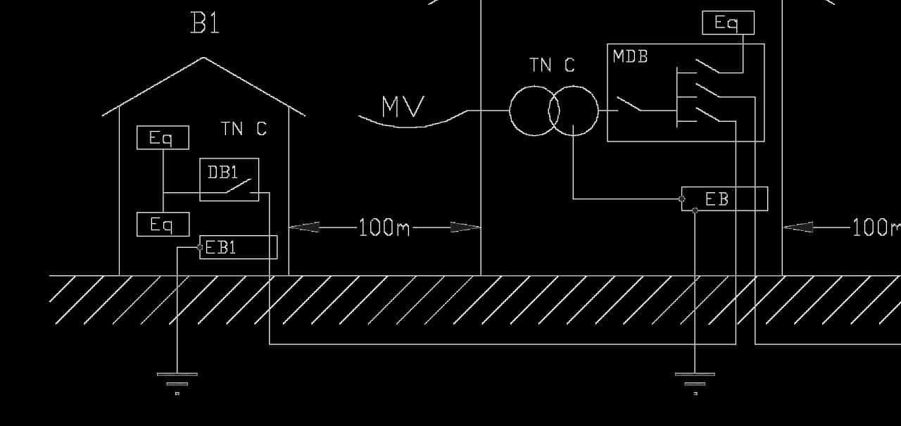 Figure 3 – Industrial installation
Key:
- B1, B2 – Building 1, 2;
- MB – Main building;
- EB – Equipotential bonding bar;
- MDB – main distribution board;
- DB – distribution board;
- Eq – Load equipment.
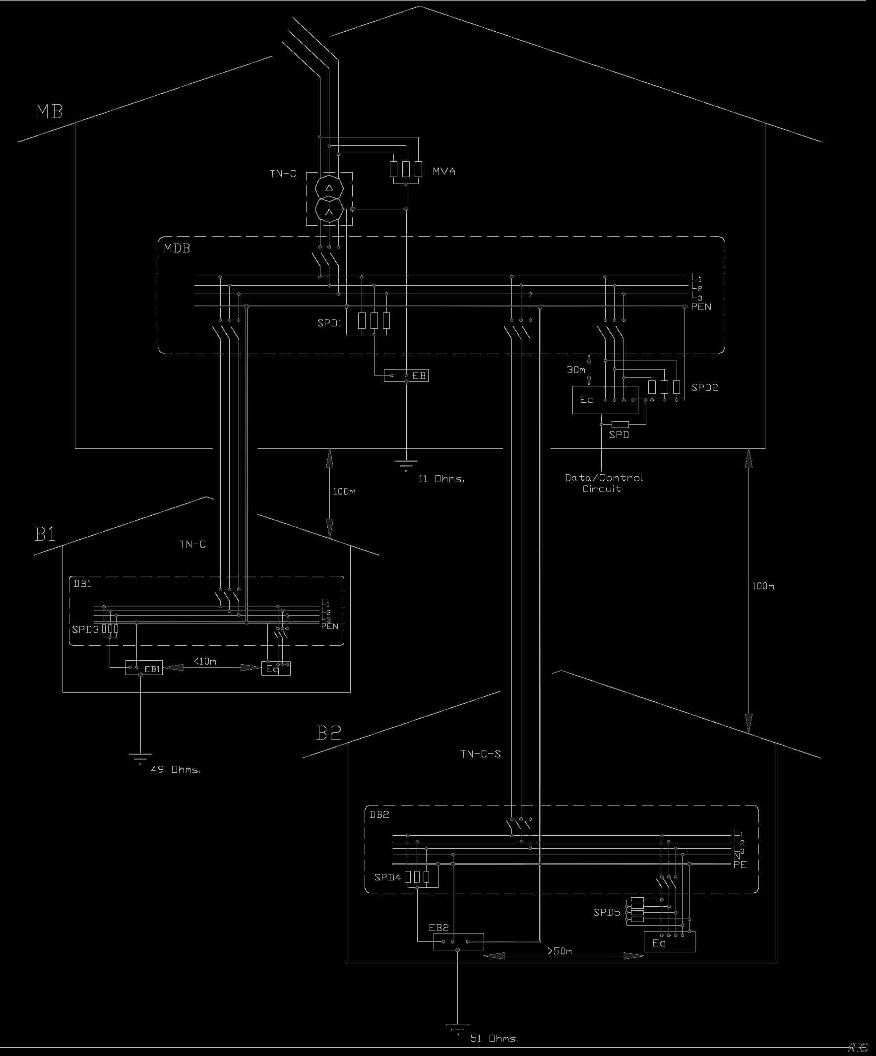 Figure 4 – Circuitry of industrial installation
Key:
- B1, B2 – Building 1, 2;
- MB – Main building;
- EB – Equipotential bonding bar;
- MDB – Main distribution board;
- Eq – Load equipment;
- PB – Panel board;
- MVA – Medium voltage surge arrester.
Read more: SPD Location in Electrical Installations of Buildings and SPD Test Classes
- IEC 61643-11-2011
- IEC 61643-12-2020
- BS 7671:2018+A2:2022
Telegram channel @asutpp_com