In electrical engineering, SPD stands for “Surge Protective Device”.
Surge protective device (SPD) (or spike suppressor, surge suppressor, surge diverter, or transient voltage surge suppressor (TVSS) is a device that contains at least one nonlinear component that is intended to limit surge voltages and divert surge currents [Source: IEC 61643-11].
NOTE – An SPD is a complete assembly, having appropriate connecting means.
The British Standard BS 7671 defined the term “surge protective device (SPD)” as follows:
Surge protective device (SPD) is a device that is intended to limit transient overvoltages and divert surge currents. It contains at least one non-linear component.
BS 7671:2018+A2:2022
The 18th edition of BS7671 mandates the inclusion of transient overvoltage protection wherever there exists a potential threat that overvoltage could cause harm or disrupt commercial operations, industry actions, or public services.
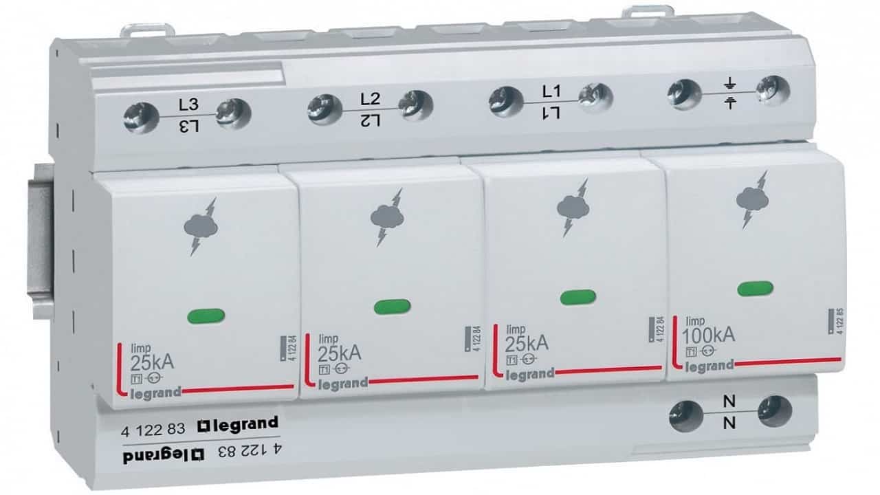 Figure 1 – Surge protective device example
The surge protective device is a component of the electrical installation protection system.
A surge protective device is designed to protect electrical equipment and electrical systems from voltage surges or transients that may occur due to lightning strikes, power switching, or other events. It diverts excess voltage away from sensitive devices, preventing damage and ensuring the safe operation of electrical equipment. SPDs are commonly used in domestic installations to safeguard appliances, computers, communication systems, and other electronic devices from potential damage caused by voltage spikes.
Your home’s electrical installation and equipment are worth protecting. Surge protection is an essential necessity used to protect your electronic equipment from voltage spikes caused by power line disturbances or direct lightning strikes. A surge protector serves as a line of defense, shielding your devices from a potentially harmful high influx of voltage that could result in irreversible damage. When a surge occurs, the protection circuit diverts the extra electricity into the earth wire, leaving your electronic equipment unharmed.
Thus, in the event of lightning strikes, lightning protection, which is also facilitated by surge protectors, is an imperative element. However, it is crucial to understand that while modern surge protectors can handle multiple minor or moderate incidents efficiently, they might not fully protect your equipment against a direct, powerful lighting strike. Hence, along with investing in a good quality surge protector, it is also recommended to unplug your valuable devices in stormy weather for maximum security.
In industrial, commercial and residential environments, SPD is commonly used in a variety of applications. These include power distribution, control cabinet management, programmable logic controllers, electronic motor controls, equipment monitoring, lighting circuits, instrumentation, medical equipment, vital loads, backup power, UPS (uninterruptible power supply), and HVAC (heating, ventilation, and air conditioning).
The wording within the regulatory framework strongly encourages the use of SPDs (Surge Protective Devices) unless a comprehensive risk assessment demonstrates that their use is unnecessary.
Examples of voltage limiting components are metal oxide varistors (MOVs) and transient voltage suppression (TVS) diodes. Voltage switching components include gas discharge tubes (GDTs) and spark gaps.
The working principle of SPDs is based on the use of metal oxide varistors (MOVs) or gas discharge tubes (GDTs) that divert the excess electrical energy away from the protected equipment.
At normal operating voltages, the SPDs are in a high-impedance state and do not affect the system. When a surge occurs, the voltage across the MOV (varistor) or GDT increases, causing it to conduct current and divert the excess energy to ground or to a neutral conductor. As a result, the voltage across the protected equipment is limited to a safe level, preventing damage to the equipment.
It is important to note that SPDs do not prevent surges from occurring; rather, they limit the voltage that reaches the equipment being protected. Additionally, surge protectors should be installed by a qualified electrician and regularly inspected to ensure they are functioning properly.
Their functioning in power systems can be described as follows.
- In the absence of surges: the surge protective device shall not have a significant influence on the operational characteristics of the system to which it is applied.
- During the occurrence of surges: the surge protector responds to surges by lowering its impedance and thus diverting surge current through it to limit the voltage (in most cases much lower than its protective level Up). The surges could initiate a power follow current through the spike suppressor depending on the SPD design (surge suppressor with power follow current).
- After the occurrence of surges: the spike suppressor recovers to a high-impedance state after the surges and extinguishes any possible power follow current.
The characteristics of SPDs are intended to achieve the above functions under normal service conditions. Normal service conditions are specified by the frequency of the power-system voltage, load current, altitude (i.e. air pressure), humidity and ambient air temperature.
There are three types of SPDs:
Type 1 SPD.
Type 1 SPD installed at the origin, e.g. main distribution board.
Type 1 SPD is characterized by a 10/350 µs current wave.
Type 2 SPD.
Type 2 SPD installed at sub-distribution boards. Combined Type 1 & 2 SPDs are available and are usually installed in consumer units.
Type 2 SPD is characterized by an 8/20 µs current wave.
Type 3 SPD.
Type 3 SPD installed close to the protected load. They must only be installed as a supplement to Type 2 SPD.
Type 3 SPD is characterized by a combination of voltage waves (1.2/50 μs) and current waves (8/20 μs).
| Direct lightning stroke | Indirect lightning stroke | ||
|---|---|---|---|
| IEC 61643-1 | Class I test | Class II test | Class III test |
| IEC 61643-11/2011 | Type 1 : T1 | Type 2 : T2 | Type 3 : T3 |
| EN/IEC 61643-11 | Type 1 | Type 2 | Type 3 |
| Former VDE 0675v | B | C | D |
| Type of test wave | 10/350 | 8/20 | 1.2/50 + 8/20 |
Table 1 – SPD standard definition
- Note 1: There T1 + T2 exist + SPD (or Type 1 + 2 SPD) combining protection of loads against direct and indirect lightning strokes.
- Note 2: some T2 SPD can also be declared as T3.
The appropriate test class or type of SPD depends on the characteristics of the site, taking into account the susceptibility of the equipment to significant surge currents and the importance of limiting the allowable voltage level to protect the connected equipment.
See Also: Classification of Surge Protective Devices (SPDs)
Main Requirements
Protection against direct contact.
These requirements are valid for accessible surge protectors where the maximum continuous operating voltage Uc is above 50 V r.m.s.
For protection against direct contact (inaccessibility of live parts), surge protective devices shall be designed in such a way that live parts cannot be touched when the surge protector is installed for the intended use.
SPDs, except SPDs classified for mounting out-of-reach-only, shall be so designed that, when they are wired and mounted as for normal use, live parts are not accessible, even after removal of parts which can be removed without the use of a tool.
The connection between the earthing terminals and all accessible parts connected thereto shall be of low resistance.
Residual current IPE.
For all SPDs with a terminal for the protective conductor, the residual current IPE shall be measured when all surge protector terminals are connected to a power supply at the reference test voltage (UREF) according to the manufacturer’s instructions.
Voltage protection level Up.
The measured limiting voltage of the surge protective devices shall not exceed the voltage protection level that is specified by the manufacturer.
Operating duty.
The surge protective device shall be capable of withstanding specified discharge currents during application of the maximum continuous operating voltage Uc without unacceptable changes in its characteristics.
Disconnectors.
The surge diverter shall have disconnectors (which can be either internal, external or both), except surge protective devices for connection N-PE in TN and/or TT systems only. Their operation shall be indicated by a corresponding status indicator.
Thermal protection.
Spike suppressors shall be protected against overheating due to degradation or overstress. This test is not performed on surge protective devices containing only voltage switching components and/or ABD devices.
Short-circuit current behaviour.
A spike suppressor shall fail without causing a hazardous condition or withstand the prospective short-circuit currents of the power system that may occur during an SPD failure.
Compliance is checked by the test in accordance with 8.3.5.3, 8.3.5.3.1 and 8.3.5.3.2 of IEC 61643-11-2011.
These tests are not performed on surge protective devices classified for outdoor use and for mounting out of reach and for SPDs for connection N-PE in TN and/or TT systems only.
Status indicators.
The manufacturer shall provide information about the function of the indicator and the actions to be taken after change of status indication.
A status indicator may be composed of two parts (one of which is not replaced on replacement of the surge protective device), linked by a coupling mechanism which can be mechanical, optical, audio, electromagnetic, etc. The part of the status indicator which is not replaced shall be capable of operating at least 50 times.
The action of the coupling mechanism which operates the non-replaced part of the status indicator may be simulated by means other than operation of the section within the replaced part of the surge protective device, e.g. a separate electromagnet or a spring.
Where there is an appropriate standard for the type of indication used, this shall be met by the non-replaced part of the status indicator, with the exception that the indicator need only be tested for 50 operations.
Insulation resistance.
The insulation resistance of the surge protective device shall be sufficient with respect to leakage currents and protection against direct contact.
Dielectric withstand.
The dielectric withstand of the surge protective device shall be sufficient with respect to insulation breakdown and protection against direct contact.
Mounting.
SPDs shall be provided with appropriate means for mounting that will ensure mechanical stability. Mechanical coding/interlock shall be provided to prevent incorrect combinations of plug-in spike suppressor modules and sockets.
External connections.
Electrical connections shall be possible using one of the following means:
- screw terminals and bolted connections;
- screwless terminals;
- insulation piercing connections;
- flat quick connect terminations;
- flying leads;
- other equally effective means;
or
- standardised plugs and/or sockets.
Compliance is checked by visual inspection.
Terminals shall be fastened to the surge protective device in such a way that they will not work loose if the clamping screws or the lock nuts are tightened or loosened. A tool shall be required to loosen the clamping screws or the lock nuts.
- a) Terminals for external conductors shall be such that the conductors may be connected so as to ensure that the necessary contact pressure is maintained permanently. The terminals shall be readily accessible under the intended conditions of use.
- b) The means for clamping the conductors in the terminals shall not serve to fix any other component, although they may hold the terminals in place or prevent them from turning.
- c) Terminals shall have adequate mechanical strength.
- d) Terminals shall be so designed that they clamp the conductor without undue damage to the conductor.
- e) Terminals shall be so designed that they clamp the conductor reliably and between metal surfaces.
- f) Terminals shall be so designed or positioned that neither a rigid solid conductor nor a wire of a stranded conductor can slip out while the clamping screws or nuts are tightened.
Air clearances and creepage distances.
The surge protective device shall have sufficient air clearances and creepage distances.
Mechanical strength.
All parts of the surge protective device relating to the protection against direct contact shall have sufficient mechanical strength.
This subclause presents hypothetical systems for domestic and industrial facilities in which spike suppressors are installed. This subclause is intended to provide information about the selection of SPDs in limited situations to illustrate the application principles. It is not intended to address the unique aspects of the conditions that exist in all facilities or systems.
Medium voltage (MV) network: overhead line 10 km.
Low voltage (LV) (230/400 V) network: overhead line 1 000 m; underground cable 200 m.
Ground flash density (NG): 2 strikes/km2/year (see 5.2.2 of IEC 61643-12-2020).
Location of the structure to be protected: on a flat area.
Structure of the electric installation: installation protected by an RCD type S at the entrance (withstand 3 kA 8/20). The short-circuit current capability at the entrance of the installation is 3 kA. There is a main electrical board at the entrance of the house (ground floor) and one subsidiary electrical board on the first floor.
Resistance of the earthing arrangement of the structure to be protected: 50 Ω.
Earthing system of the low-voltage network – TT system. One phase and neutral distributed.
Nature of devices to be protected: electronic washing machine, computer, alarm at the entrance, video tape recorder and TV set, etc.
Due to the risk analysis it is probable that there is some interest in using domestic surge protection devices (high value of NG, overhead lines both on MV and low voltage distribution system side of the transformer, electronic devices, etc.).
Due to the overhead lines medium lightning currents are expected; nominal discharge current (In) ≥ 5 kA 8/20 per wire at the entrance.
At the entrance, an alarm is to be protected (sensitive equipment); Up ≤ 1,5 kV. This may be achieved by a one-port surge suppressor tested by class II tests with Up = 1,5 kV.
At the entrance, the short-circuit current capability is 3 kA RMS; short-circuit withstand of the SPD ≥3 kA RMS. For this the manufacturer recommends use of a fuse or the short-circuit breaking characteristics of an RCD circuit-breaker (back-up protection). If an RCD type S circuit-breaker is used at the entrance, the continuity of service is not assured for incoming surges in excess of 3 kA 8/20.
No additional protection against indirect contact is needed due to the presence of the RCD. A thermal disconnector is incorporated in the spike suppressor itself. As it is a TT system and in order to avoid too high a stress between phase and neutral: it is recommended that an spike suppressor having three modes of protection be used (phase to neutral, neutral to earth and phase to earth).
The other devices to be protected need only protection between phase and neutral as the earth is not connected to them, except the washing machine where the earth is present for safety purposes. In this case, protection between phase and earth and neutral and earth may be necessary.
NOTE. Additional protection may be necessary if the TV antenna is earthed.
As the distance between the surge protective device at the entrance and the other devices, especially on the first floor, is high (10 m and 20 m respectively), other surge protective devices are necessary close to the devices to be protected. One should be located close to the washing machine and another one close to the video tape recorder and TV set. Another one is connected at the first-floor electrical board but could be connected direct on the computer plug as well (distance is small between this panel and the computer).
The other SPDs should see a lower surge current. Also, In = 2 kA class II tests is sufficient. Up = 0,8 kV is then proposed in the manufacturer’s catalogue. The distance of 20 m is sufficient to provide decoupling between the surge protective device located at the entrance and the first-floor one. But the 10 m between the entrance surge protective device and the other ground-floor SPDs is not sufficient to provide adequate decoupling due to the low value of Up = 0,8 kV. It is then better to choose another surge protective device with Up = 1,5 kV, for example, for the other ground-floor surge protective devices.
For these surge protective devices, the short-circuit current at their location is low and the manufacturer has incorporated the necessary disconnectors (thermal and short-circuit). See Figure 2.
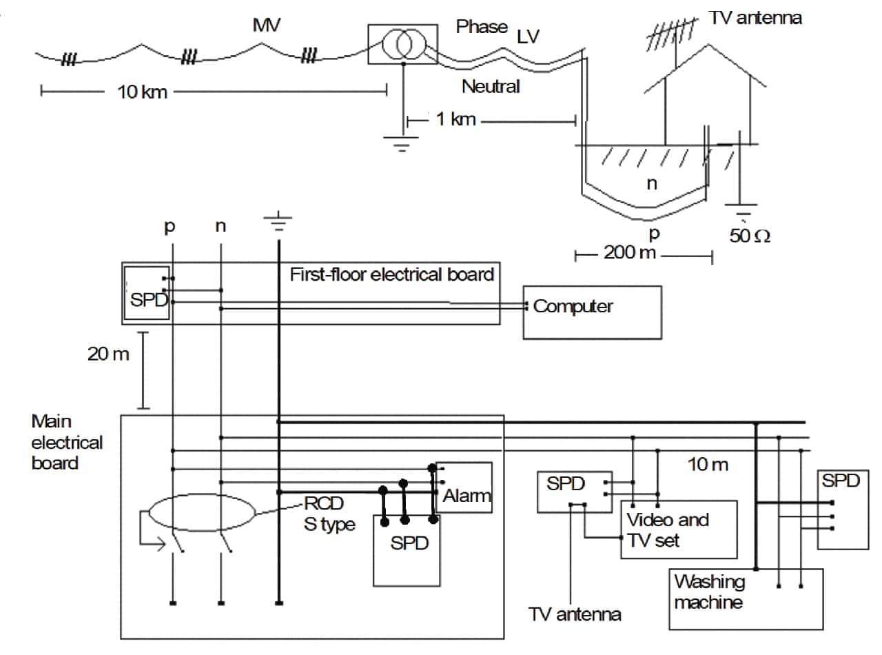 Figure 2 – Domestic application of SPD
See: Electrical Surge Protection Devices for Industrial Facilities