Equipotential bonding (EPB) is a set of electric connections intended to achieve equipotentiality between conductive parts [Source: IEC 60050-195-2021].
The British Standard BS 7671 defines the term “equipotential bonding” as follows:
Equipotential bonding is an electrical connection maintaining various exposed-conductive-parts and extraneous-conductive-parts at substantially the same potential.
BS 7671:2018+A1:2020
Protective-equipotential bonding is an equipotential bonding for the purposes of electrical safety.
 Figure 1. The person does not get an electric shock when the second fault occurs and the equipotential bonding line is well connected [source]
Protective-equipotential-bonding is a provision whereby items are bonded together to avoid hazardous touch voltages.
The protective-equipotential-bonding system shall consist of one or a suitable combination of two or more of the elements below:
- protective-equipotential-bonding in equipment;
- earthed or unearthed protective-equipotential-bonding in the installation;
- protective conductor (PE);
- PEN, PEL or PEM conductor;
- protective screen;
- earthed point of the source or artificial neutral point;
- earth electrode (including earth electrodes for potential grading);
- earthing conductor.
The equipotential bonding system of a high-voltage installation or system shall be connected to earth because of the special risks, which may be present, e.g. the danger of high touch and step voltage and of exposed-conductive-parts becoming live due to electrical discharge. The impedance to earth of the earthing arrangement shall be rated so that no hazardous touch voltage can occur. Exposed-conductive-parts, which can become live under fault conditions, shall be connected to the earthing arrangement.
NOTE:
Equipotential bonding system is an interconnection of conductive parts providing equipotential bonding between those parts.
IEC 60050-195-2021
Accessible conductive parts which could acquire a hazardous effective touch voltage in the event of a failure of basic protection, i.e. exposed-conductive-parts and any protective screen, shall be connected to the protective-equipotential-bonding system.
NOTE. A conductive part of electrical equipment which can only become live through contact with an exposed-conductive-part which has become live, is not considered to be an exposed-conductive-part itself.
The protective-equipotential-bonding system shall be of sufficiently low impedance to avoid hazardous potential difference between conductive parts in case of an insulation failure. Where necessary the protective-equipotential-bonding system shall be used in association with a protective device operated by the fault current. The maximum difference in potential and its duration shall be based on IEC TR 60479-5.
This may necessitate consideration of the relative impedance values of the different elements of a protective-equipotential-bonding system.
The difference in potential need not be considered if the impedance of the circuit limits the steady-state touch current in the case of a single fault so that it cannot exceed 3,5 mA a.c., r.m.s. or 10 mA d.c. when measured in accordance with IEC 60990.
In some environments or situations, e.g. medical locations (see limit values in IEC 60601-1), highly conductive locations, wet areas and similar areas, the limit values need to be lower.
All parts of the protective-equipotential-bonding system shall be so dimensioned that thermal and dynamic stresses which are likely to occur do not impair the characteristics of the protective-equipotential-bonding system, e.g. as a consequence of a failure or bridging of basic insulation.
All parts of the protective-equipotential-bonding system shall be capable of withstanding all internal and external influences (including mechanical, thermal and corrosive) which may be expected.
Where a component of an installation, system or equipment is intended to be removed, the protective-equipotential-bonding for any other part of the installation, system or equipment shall not be interrupted when removing the component unless the electrical supply to the other part is first disconnected.
With the exception described below, no element of the protective-equipotential-bonding system shall contain any device which might reasonably be expected to break the electrical continuity or introduce significant impedance. This requirement may be dispensed with by technical committees for the verification of the continuity of protective conductors or for measuring of the current of the protective conductor.
Where elements of the protective-equipotential-bonding system can be interrupted by the same coupler or plug-and-socket-outlet device as the relevant supply conductors, the protective-equipotential-bonding system shall not be interrupted before the supply conductors. The protective-equipotential-bonding shall be re-established not later than when the supply conductors are reconnected. These requirements do not apply where interruption and reconnection are possible only with the equipment in de-energized condition.
In high-voltage installations, systems and equipment, the protective-equipotential-bonding system shall not be interrupted before the main contact has reached an isolating distance which can withstand the equipment rated impulse withstand voltage.
Conductors of the protective-equipotential-bonding system, whether insulated or bare, shall be readily distinguishable by shape, location, marking or colour, except those conductors which cannot be disconnected without destruction, e.g. in wire-wrap and similar wiring in electronic equipment and tracks on printed wiring boards. If identification by colour is used, it shall be in accordance with IEC 60445.
Conductors used only for functional earthing shall not have insulation coloured green-and-yellow.
In each building, incoming metallic parts which are liable to introduce a dangerous potential difference and do not form part of the electrical installation shall be connected to the main earthing terminal by protective bonding conductors; examples of such metallic parts may include:
- pipes supplying services into the building, for example gas, water, district heating systems;
- structural extraneous-conductive-parts;
- accessible reinforcement of constructional reinforced concrete.
Where such conductive parts originate outside the building, they shall be bonded as close as practicable to their point of entry within the building.
Metallic pipes entering the building having an insulating section installed at their entrance need not be connected to the protective equipotential bonding.
NOTE. Subclause 542.4.1 of IEC 60364-5-54:2011 lists other connections which are to be made to the main earthing terminal.
Protective measure in which:
- basic protection is provided by basic insulation between hazardous-live-parts and exposed-conductive-parts, and
- fault protection is provided by a protective equipotential bonding system preventing hazardous voltages between simultaneously accessible exposed and extraneous-conductive-parts.
Additional protection by supplementary equipotential bonding is a provision whereby dangerous touch voltages are avoided by bonding of items.
Supplementary equipotential bonding is provided as an additional protective provision where:
- a) basic protection is provided by one of the provisions of basic insulation or protective barriers or enclosures, and
- b) fault protection is provided by protective earthing, protective equipotential bonding and automatic disconnection in the event of a fault.
This protective provision will help avoid hazardous voltages between exposed-conductive-parts and extraneous-conductive-parts which can be touched simultaneously.
In locations intended for livestock, supplementary bonding shall connect all exposed-conductive-parts and extraneous-conductive-parts that can be touched by livestock. Where a metal grid is laid in the floor, it shall be included within the supplementary bonding of the location (see Figure 2).
It is recommended that spaced floors made of prefabricated concrete elements be part of the equipotential bonding (see Figure 2). The supplementary equipotential bonding and the metal grid, if any, shall be erected so that it is durably protected against mechanical stresses and corrosion.
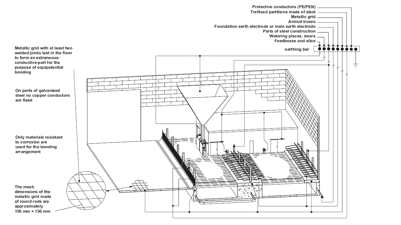 Figure 2. Example of supplementary equipotential bonding within a cattle shed
Supplementary protective-equipotential-bonding is used in addition to:
- basic protection by basic insulation between hazardous-live-parts and exposed-conductive-parts, and
- fault protection by applying protective-equipotential-bonding to avoid hazardous voltages between exposed-conductive-parts and extraneous-conductive-parts which can be touched simultaneously.
Note 1: Supplementary protective equipotential bonding is considered as an addition to fault protection.
Note 2: The use of supplementary protective bonding does not exclude the need to disconnect the supply for other reasons, for example protection against fire, thermal stresses in equipment, etc.
Note 3: Supplementary protective bonding may involve the entire installation, a part of the installation, an item of apparatus, or a location.
Note 4: Additional requirements may be necessary for special locations, (see the corresponding Part 7 of IEC 60364), or for other reasons.
Supplementary protective equipotential bonding shall include all simultaneously accessible exposed-conductive-parts of fixed equipment and extraneous-conductive-parts including where practicable the main metallic reinforcement of constructional reinforced concrete. The equipotential bonding system shall be connected to the protective conductors of all equipment including those of socket-outlets.
The resistance R between simultaneously accessible exposed-conductive-parts and extraneous-conductive-parts shall fulfil the following condition:
R ≤ 50 V / Ia in a.c. systems
R ≤ 120 V / Ia in d.c. systems
where
Ia is the operating current in A of the protective device
– for residual current protective devices (RCDs), IΔn
– for overcurrent devices, the 5 s operating current.
Earthing and equipotential bonding have the fundamental goal of safety and electromagnetic compatibility (EMC). Safety is achieved by limiting the touch voltage and the return path of fault currents while EMC is achieved by avoiding differences in potential and providing a screening effect. Earthing and bonding are essential parts of any electrical system.
For more information on this subclause, click here: Earth electrode: What it is, Requirements, Resistance
Exposed-conductive-parts of information technology and electronic equipment within a building are interconnected via protective conductors.
For dwellings where normally a limited amount of electronic equipment is in use, a protective conductor network in the form of a star network may be acceptable; see Figure 3
For commercial and industrial buildings and similar buildings containing multiple electronic applications, a common equipotential bonding system is useful in order to comply with the EMC requirements of different types of equipment; see Figure 5.
The four basic structures described in the following subclauses may be used, depending on the importance and vulnerability of equipment.
An equipotential bonding network in the form of a bonding ring conductor, BRC, is shown in Figure 6 on the top-floor of the structure. The BRC should preferably be made of copper, bare or insulated, and installed in such a manner that it remains accessible everywhere, e.g. by using a cable-tray, metallic conduit (see the IEC 61386 series), surface mounted method of installation or cable trunking. All protective and functional earthing conductors may be connected to the BRC.
This type of network is applicable to small installations associated with dwellings, small commercial buildings, etc., and from a general point of view to equipment, that is not interconnected by signal cables; see Figure 3.
 Figure 3 – Examples of protective conductors in star network [Based on figure 44.R13 IEC 60364-4-44-2018]
This type of network is applicable to small installations with different small groups of interconnected communicating equipment. It enables the local dispersion of currents caused by electromagnetic interference; see Figure 4.
 Figure 4 – Example of multiple meshed bonding star network [Based on figure 44.R14 IEC 60364-4-44-2018]
This type of network is applicable to installations with high density of communicating equipment corresponding to critical applications; see Figure 5.
A meshed equipotential bonding network is enhanced by the existing metallic structures of the building. It is supplemented by conductors forming the square mesh.
The mesh-size depends on the selected level of protection against lightning, on the immunity level of equipment part of the installation and on frequencies used for data transmission.
Mesh-size shall be adapted to the dimensions of the installation to be protected, but shall not exceed 2 m × 2 m in areas where equipment sensitive to electromagnetic interferences is installed.
It is suitable for protection of private automatic branch exchange equipment (PABX) and centralized data processing systems.
In some cases, parts of this network may be meshed more closely in order to meet specific requirements.
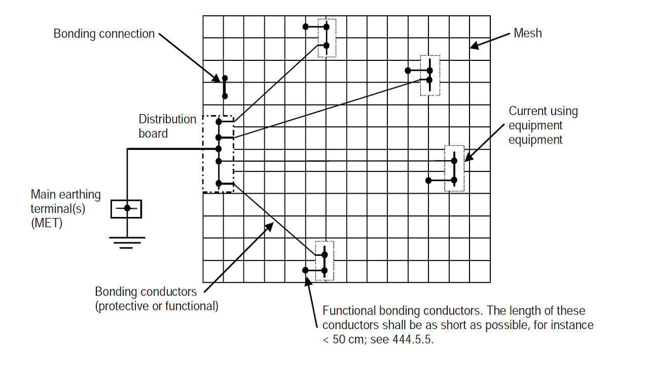 Example 5 – Example of a common meshed bonding star network [Based on figure 44.R15 IEC 60364-4-44-2018]
The area covered by a mesh shall have overall dimensions; the mesh-size refers to the dimensions of square spaces enclosed by the conductors forming the mesh.
For buildings with several floors, it is recommended that, on each floor, an equipotential bonding system be installed; see Figure 6 for examples of bonding networks in common use; each floor is a type of network. The bonding systems of the different floors should be interconnected, at least twice, by conductors.
 Example 6 – Example of equipotential bonding networks in structures without lightning protection systems [Based on figure 44.R16 IEC 60364-4-44-2018]
Read more on the topic in this article: Functional Earthing Conductor (FE): Definition, Example, Color and Symbol
The following additional specifications are intended to reduce the influences of electromagnetic disturbances on the information technology equipment operation.
In severe electromagnetic environments, it is recommended that the common meshed bonding star network described in subclause “Multiple meshed bonding star network” be adopted.
Equipotential bonding designed as a bonding ring network shall have the following minimum dimensions:
- flat copper cross-section: 30 mm × 2 mm;
- round copper diameter: 8 mm.
Bare conductors shall be protected against corrosion at their supports and on their passage through walls.
The following parts shall also be connected to the equipotential bonding network:
- conductive screens, conductive sheaths or armouring of data transmission cables or of information technology equipment;
- earthing conductors of antenna systems;
- earthing conductors of the earthed pole of DC supply for information technology equipment;
- functional earthing conductors.
Where an earthing busbar is required for functional purposes, the main earthing terminal (MET) of the building may be extended by using an earthing busbar. This enables information technology installations to be connected to the main earthing terminal by the shortest practical route from any point in the building. Where the earthing busbar is erected to support the equipotential bonding network of a significant amount of information technology equipment in a building, it may be installed as a bonding ring network; see Figure 15.
NOTE 1: The earthing busbar may be bare or insulated.
NOTE 2: The earthing busbar should preferably be installed so that it is accessible throughout its length, e.g. on the surface of trunking. To prevent corrosion, it may be necessary to protect bare conductors at supports and where they pass throughout walls.
The effectiveness of the earthing busbar depends on the routing and the impedance of the conductor employed. For installations connected to a supply having a capacity of 200 A per phase or more, the cross-sectional area of the earthing busbar shall be not less than 50 mm2 copper and shall be dimensioned in accordance with subclause “Measures to reduce EMI” k).
NOTE: This statement is valid for frequencies up to 10 MHz.
Where the earthing busbar is used as part of a DC return current path, its cross-sectional area shall be dimensioned according to the expected DC return currents. The maximum DC voltage drop along each earthing busbar, dedicated as DC distribution return conductor, shall be designed to be less than 1 V.
Earth-free local equipotential bonding is intended to prevent the appearance of a dangerous touch voltage.
Equipotential bonding conductors shall interconnect all simultaneously accessible exposed-conductive-parts and extraneous-conductive-parts.
The local equipotential bonding system shall not be in electrical contact with earth directly, nor through exposed-conductive-parts, nor through extraneous-conductive-parts.
Precautions shall be taken to ensure that persons entering the equipotential location cannot be exposed to a dangerous potential difference, in particular, where a conductive floor insulated from earth is connected to the earth-free equipotential bonding system.