Overvoltage in an electric power system is a voltage:
- between one line conductor and earth or across a longitudinal insulation having a peak value exceeding the corresponding peak of the highest voltage of the system divided by √3 or;
- between phase conductors having a peak value exceeding the amplitude of the highest voltage of the system.
[Source: IEC 60050-614:2016]
Transient overvoltages, which are also referred to as voltage surges, are brief and sudden deviations or fluctuations that arise within the electrical power network, and may inflict harm on highly-sensitive electrical apparatus. These overvoltages can be instigated by a variety of circumstances, including:
- Lightning strikes. Lightning is considered a principal factor behind the emergence of transient overvoltages within electrical power networks. In situations where lightning strikes near a power line, it can produce a voltage surge that may journey through the line and inflict harm on the apparatus.
- Switching operations. When switching operations occur, such as the activation or deactivation of a circuit breaker or the separation of a power line, an abrupt alteration arises within the electrical current flow, which leads to a transient overvoltage.
- System faults. Electrical faults, such as short circuits or ground faults, may result in overvoltages within the electrical system.
- Electromagnetic interference. Electromagnetic interference (EMI) originating from nearby electrical devices, such as motors or transformers, can result in overvoltages within the electrical system.
- Capacitive coupling. Capacitive coupling arises when two conductors, such as power lines or cables, are in proximity to each other but are not connected. The capacitance between the two conductors may give rise to a voltage surge.
- Power quality issues. Poor power quality, such as voltage dips or sags, may result in overvoltages when the voltage returns to normal.
The following subclauses consider four situations, which generally cause the most severe temporary overvoltages such as defined in IEC 60050-614:
- fault between the high-voltage system(s) and earth;
- loss of the neutral in a low-voltage system;
- accidental earthing of a low-voltage IT system;
- short-circuit in the low-voltage installation.
Overvoltage protection is protection intended to operate when the power system voltage is in excess of a predetermined value [Source: IEC 60050-448-1995].
Temporary overvoltage is a power frequency overvoltage of relatively long duration.
IEC 60050-614-2016
Note 1 to entry: A temporary overvoltage is undamped or weakly damped. In some cases its frequency may be several times smaller or greater than power frequency.
The rules of this subclause provide requirements for the safety of low-voltage installation in the event of:
- a fault between the high-voltage system and earth in the transformer substation that supplies the low-voltage installation,
- a loss of the supply neutral in the low-voltage system,
- a short-circuit between a line conductor and neutral,
- an accidental earthing of a line conductor of a low-voltage IT-system.
The requirements for the earthing arrangement at the transformer substation are given in IEC 61936-1.
As this subclause covers faults between a high-voltage line and the earth in the HV/LV substation, it gives rules for the designer and installer of the substation. It is necessary to have the following information concerning the high-voltage system:
- quality of the system earthing;
- maximum level of earth fault current;
- resistance of the earthing arrangement.
In case of a fault to earth on the HV-side of the substation, the following types of overvoltage may affect the LV-installation:
- power frequency fault-voltage (Uf);
- power frequency stress-voltages (U1 and U2).
Table 1 provides the relevant methods of calculation for the different types of overvoltages.
NOTE 1 – Table 1 deals with IT systems with a neutral point only. For IT systems with no neutral point, the formulae should be adjusted accordingly.
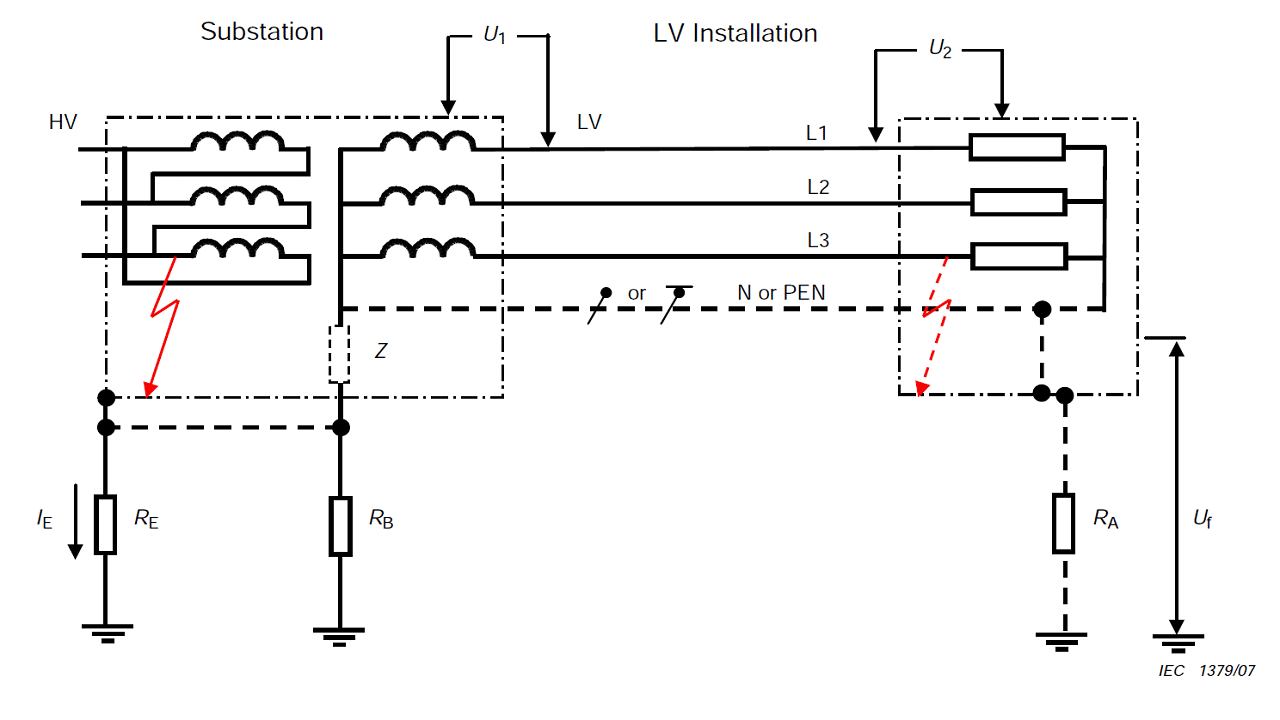 Figure 1 – Representative schematic sketch for possible connections to earth in substation and LV-installation and occurring overvoltages in case of faults [2]
Key:
- IE part of the earth fault current in the high-voltage system that flows through the earthing arrangement of the transformer substation.
- RE resistance of the earthing arrangement of the transformer substation.
- RA resistance of the earthing arrangement of the exposed-conductive-parts of the equipment of the low-voltage installation.
- RB resistance of the earthing arrangement of the low-voltage system neutral, for low-voltage systems in which the earthing arrangements of the transformer substation and of the low-voltage system neutral are electrically independent.
- Uo in TN- and TT-systems: nominal a.c. r.m.s. line voltage to earth in IT-systems: nominal a.c. voltage between line conductor and neutral conductor or mid point conductor, as appropriate.
- Uf power-frequency fault voltage that appears in the low-voltage system between exposed-conductive-parts and earth for the duration of the fault.
- U1 power-frequency stress voltage between the line conductor and the exposed-conductive-parts of the low-voltage equipment of the transformer substation during the fault.
- U2 power-frequency stress voltage between the line conductor and the exposed-conductive-parts of the low-voltage equipment of the low-voltage installation during the fault.
The power-frequency stress voltage (U1 and U2) is the voltage that appears across the insulation of low-voltage equipment and across surge protective devices connected to the low-voltage system.
Where high- and low-voltage earthing systems exist in proximity to each other, two practices are presently used:
- interconnection of all high-voltage (RE) and low-voltage (RB) earthing systems;
- separation of high-voltage (RE) from low-voltage (RB) earthing systems.
The general method used is interconnection. The high- and low-voltage earthing systems shall be interconnected if the low-voltage system is totally confined within the area covered by the high-voltage earthing system (see IEC 61936-1).
NOTE 2 – Details of the different types of system earthing (TN, TT, IT) are shown in IEC 60364-1.
| Table 1 – Power-frequency stress voltages and power-frequency fault voltage in low-voltage system [source: Table 44.A1 of IEC 60364-4-44-2018] | ||||
| Types of system earthing | Types of earth connections | U1 | U2 | Uf |
| TT | RE and RB connected | Uo *) | RE × IE + Uo | 0 *) |
| RE and RB separated | RE × IE + Uo | Uo *) | 0 *) | |
| TN | RE and RB connected | Uo *) | Uo *) | RE × IE **) |
| RE and RB separated | RE × IE + Uo | Uo *) | 0 *) | |
| IT | RE and Z connected RE and RA separated |
Uo *) | RE × IE + Uo | 0 *) |
| Uo × √3 | RE × IE + Uo × √3 | RA × Ih | ||
| RE and Z connected RE and RA interconnected |
Uo *) | Uo *) | RE × IE | |
| Uo × √3 | Uo × √3 | RE × IE | ||
| RE and Z separated RE and RA separated |
RE × IE + Uo | Uo *) | 0 *) | |
| RE × IE + Uo × √3 | Uo × √3 | RA × Id | ||
|
*) No consideration needs to be given. **) See “Magnitude and duration of power-frequency fault voltage” second paragraph. |
NOTE 3: – With existing earth fault in the installation.
NOTE 4 – The requirements for U1 and U2 are derived from design criteria for insulation of low-voltage equipment with regard to temporary power- frequency overvoltage (see also Table 2).
NOTE 5 – In a system whose neutral is connected to the earthing arrangement of the transformer substation, such temporary power-frequency overvoltage is also to be expected across insulation which is not in an earthed enclosure when the equipment is outside a building.
NOTE 6 – In TT- and TN-systems the statement “connected” and “separated” refers to the electrical connection between RE and RB. For IT-systems it refers to the electrical connection between RE and Z and the connection between RE and RA.
The following additional symbols are used in respect of IT-systems in which the exposed-conductive-parts of the equipment of the low-voltage installation are connected to an earthing arrangement that is electrically independent of the earthing arrangement of the transformer substation.
- Ih fault current that flows through the earthing arrangement of the exposed-conductiveparts of the equipment of the low-voltage installation during a period when there is a high-voltage fault and a first fault in the low-voltage installation (see Table 1).
- Id fault current that flows through the earthing arrangement of the exposed-conductive-parts of the low-voltage installation during the first fault in a low-voltage system (see Table 1).
- Z impedance (e.g. IMD internal impedance, artificial neutral impedance) between the low-voltage system and an earthing arrangement.
NOTE 7: An earthing arrangement may be considered electrically independent of another earthing arrangement if a rise of potential with respect to earth in one earthing arrangement does not cause an unacceptable rise of potential with respect to earth in the other earthing arrangement. See IEC 61936-1.
The magnitude and the duration of the fault voltage Uf (as calculated in Table 1) which appears in the LV installation between exposed-conductive-parts and earth, shall not exceed the values given for Uf by the curve of Figure 2 for the duration of the fault.
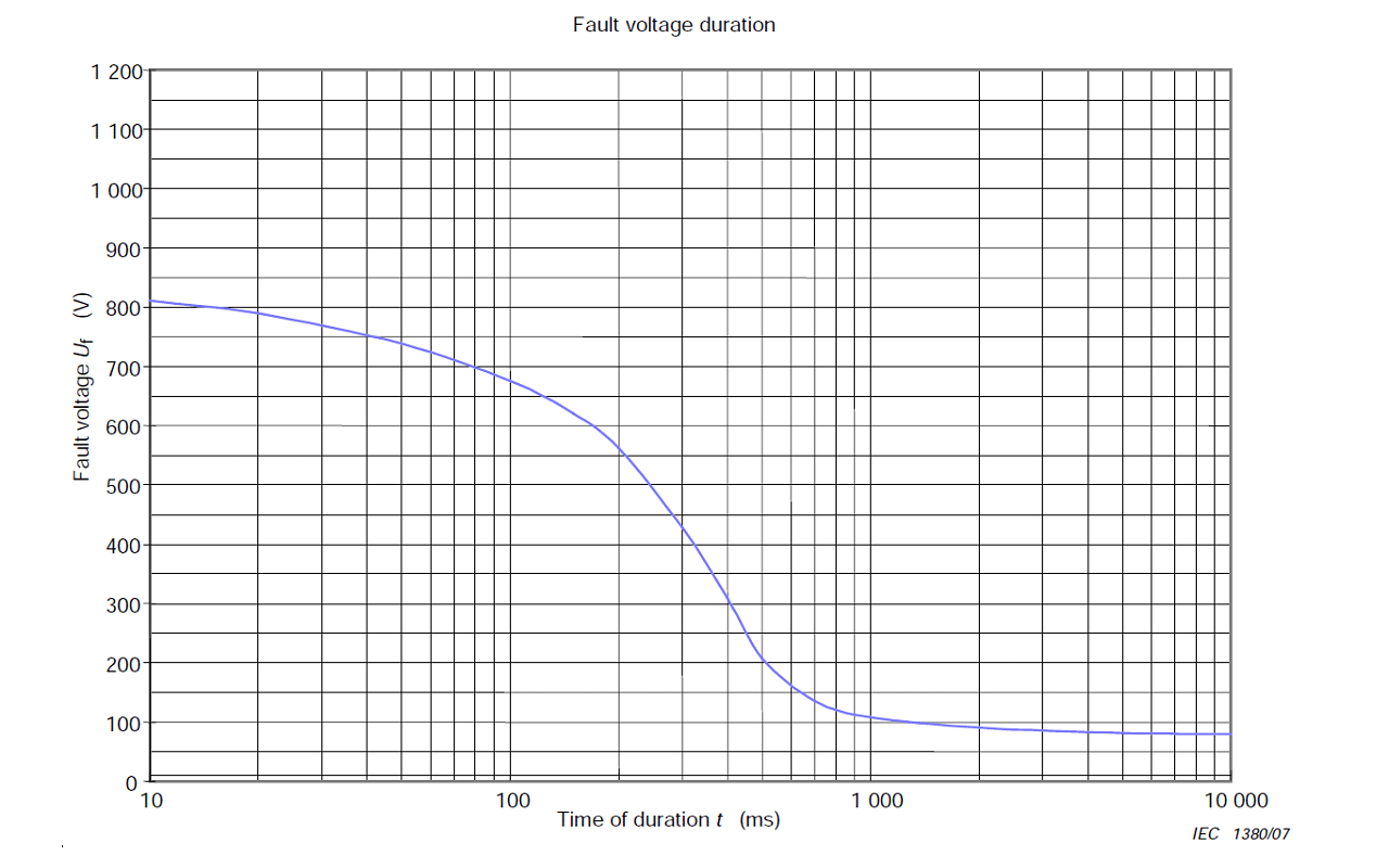 Figure 2 – Tolerable fault voltage due to an earth-fault in the HV system [2]
NOTE. The curve shown in Figure 2 is taken from IEC 61936-1. On the basis of probabilistic and statistical evidence this curve represents a low level of risk for the simple worst case where the low voltage system neutral conductor is earthed only at the transformer substation earthing arrangements. Guidance is provided in IEC 61936-1 concerning other situations.
Normally, the PEN conductor of the low-voltage system is connected to earth at more than one point. In this case, the total resistance is reduced. For these multiple grounded PEN conductors, Uf can be calculated as:
Uf = 0,5 RE ×IE
The magnitude and the duration of the power-frequency stress voltage (U1 and U2) as calculated in Table 1 of the low-voltage equipment in the low-voltage installation due to an earth fault in the high-voltage system shall not exceed the requirements given in Table 2.
| Duration of the earth fault in the high-voltage system, t | Permissible power-frequency stress voltage on equipment in low-voltage installations, U |
| > 5 s | Uo + 250 V |
| ≤ 5 s | Uo + 1 200 V |
Table 2 – Permissible power-frequency stress voltage [2]
NOTE – In systems without a neutral conductor, Uo shall be the line-to-line voltage.
NOTE – The first line of the table relates to high-voltage systems having long disconnection times, for example, isolated neutral and resonant earthed high-voltage systems. The second line relates to high-voltage systems having short disconnection times, for example low-impedance earthed high-voltage systems. Both lines together are relevant design criteria for insulation of low-voltage equipment with regard to temporary power frequency
overvoltage, see IEC 60664-1.
NOTE – In a system whose neutral is connected to the earthing arrangement of the transformer substation, such temporary power-frequency overvoltage is also to be expected across insulation which is not in an earthed enclosure when the equipment is outside a building.
Where required by Table 1, the permissible power-frequency stress voltage shall not exceed the value given in Table 2.
Where required by Table 1, the permissible power-frequency fault voltage shall not exceed the value given in Figure 2.
To fulfil the above requirements, coordination between the HV-system operator and the LV-system installer is necessary. Compliance with the above requirements mainly falls into the responsibility of the substation installer/owner/operator who needs also to fulfil requirements provided by IEC 61936-1. Therefore the calculation for U1, U2 and Uf is normally not necessary for the LV-system installer.
Possible measures to fulfil the above requirements are e.g.:
- separation of earthing arrangement between HV and LV;
- change of LV system earthing;
- reduction of earth resistance RE.
Consideration shall be given to the fact that, if the neutral conductor in a multi-phase system is interrupted, basic, double and reinforced insulation as well as components rated for the voltage between line and neutral conductors can be temporarily stressed with the line-to-Iine voltage. The stress voltage can reach up to U = √3 Uo.
Consideration shall be given to the fact that, if a line conductor of an IT system is earthed accidentally, insulation or components rated for the voltage between line and neutral conductors can be temporarily stressed with the line-to-Iine voltage. The stress voltage can reach up to U = √3 Uo.
Consideration shall be given to the fact that if a short-circuit occurs in the low-voltage installation between a phase conductor and the neutral conductor, the voltage between the other line conductors and the neutral conductor can reach the value of 1,45 x Uo for a time up to 5 s.
Transient overvoltage is an overvoltage with a duration of a few milliseconds or less, oscillatory or non-oscillatory, usually highly damped.
IEC 60050-614-2016
Note 1 to entry: Transient overvoltages may be immediately followed by temporary overvoltages. In such cases the two overvoltages are considered as separate events.
Note 2 to entry: IEC 60071-1 defines three types of transient overvoltages, namely slow-front overvoltages, fast-front overvoltages and very fast-front overvoltages according to their time to peak, tail or total duration, and possible superimposed oscillations.
This subclause specifies requirements for protection of electrical installations against transient overvoltages of atmospheric origin transmitted by the supply distribution system including direct strikes to the supply system and against switching overvoltages. This subclause does not specify requirements for protection against transient overvoltage due to direct or nearby lightning strokes on the structure.
NOTE 1. For risk management for protection against transient overvoltage due to direct or nearby lightning strokes on the structure, see IEC 62305-2.
In general, switching overvoltages have lower amplitude than transient overvoltages of atmospheric origin and therefore the requirements regarding protection against transient overvoltages of atmospheric origin normally cover protection against switching overvoltages.
If no transient overvoltage protection against disturbances of atmospheric origin is installed, protection against switching overvoltages may need to be provided.
NOTE 2. Overvoltages due to switching can be longer in duration and can contain more energy than the transient overvoltages of atmospheric origin.
The characteristics of transient overvoltages of atmospheric origin depend on factors such as:
- the nature of the supply distribution system (underground or overhead);
- the possible existence of at least one surge protective device (SPD) upstream of the origin of the installation;
- the voltage level of the supply system.
NOTE 3. As regards transient overvoltages of atmospheric origin, no distinction is made between earthed and unearthed systems.
Protection against transient overvoltages is provided by the installation of surge protective devices (SPDs).
If there is a need for SPDs on the power supply lines, additional SPDs on other Iines such as telecom lines are also recommended.
This subclause does not apply to installations where the consequences caused by overvoltages affect:
- a) structures with risk of explosion;
- b) structures where the damage may also involve the environment (e.g. chemical or radioactive emissions).
Protection against transient overvoltage shall be provided where the consequence caused by overvoltage affects:
- a) human life, e.g. safety services, medical care facilities;
- b) public services and cultural heritage, e.g. loss of public services, IT centres, museums;
- c) commercial or industrial activity, e.g. hotels, banks, industries, commercial markets, farms.
For all other cases, a risk assessment shall be performed in order to determine if protection against transient overvoltage is required. If the risk assessment is not performed, the electrical installation shall be provided with protection against transient overvoltage.
However the transient overvoltage protection is not required for single dwelling units where the total economic value of the electrical installation to be protected is less than 5 times the economic value of the SPD located at the origin of the installation.
Protection against switching overvoltages should be considered in the case of equipment likely to produce switching overvoltages or disturbances exceeding the values according to the overvoltage category of the installation e.g. where a LV generator supply the installation or where inductive or capacitive loads (e.g. motors, transformers, capacitor banks, etc.), storage units or high current loads are installed.
For a low-voltage installation supplied from a high-voltage distribution network through a separate transformer (i.e. an industrial application), additional means for protection against overvoltages due to lightning should be installed on the high-voltage side of the transformer.
NOTE 1: In Finland protection against transient overvoltage is not mandatory if an installation is supplied by underground cable. When the installation is supplied by overhead line, a risk assessment should be performed.
NOTE 2: In Germany, groups of individuals, e.g. large residential buildings, churches, offices, schools protection against overvoltages shall be provided.
NOTE 3: In Spain, according to the Royal Decree 1053/2014, Clause 6.4 of the ITC-BT-52, all the circuits intended to supply energy to electric vehicles must be protected against transient overvoltages.
NOTE 4: In the UK, for all other cases, a risk assessment shall be performed in order to determine if protection against transient overvoltage is required. If the risk assessment is not performed, the electrical installation shall be provided with protection against transient overvoltage, except for single dwelling units where the total value of the installation and equipment therein, does not justify such protection. The last paragraph of this subclause is not applicable in the UK as it is considered out of scope because it will involve work above 1 000 V.
NOTE 5: In India, protection against overvoltage protection shall be provided where over voltages affect individuals e.g. residential buildings and small offices if the risk assessment requires the protection against transient over voltages of atmospheric origin. If no risk assessment is performed protection against transient over voltages of atmospheric origin shall be provided, except for single dwellings where only overvoltage category III or IV equipment are the only equipment at this location.
NOTE 1. For protection of a structure and its electrical systems against lightning and surges of atmospheric origin, IEC 62305 applies.
You can find out more about the risk assessment method on our special page: SPD Calculator – Calculated Risk Level (CRL) Calculation
On this page you will also find a handy calculator for calculating CRL (calculated risk level). Depending on the value of the CRL, a decision can be made whether or not to use SPD protection.
This subclause gives information on the overvoltage category of the equipment.
Rated impulse voltages for equipment selected according to the nominal voltage are provided to distinguish different levels of availability of equipment with regard to continuity of service and an acceptable risk of failure.
Inherent overvoltage control based only on the impulse voltage withstand of the equipment in accordance with IEC 60664-1 might not be sufficient, because:
- transient overvoltages transmitted by the supply distribution system are not significantly attenuated downstream in most installations. Insulation coordination can be achieved in the whole installation, by transient overvoltage protection of the equipment corresponding to the classified rated impulse voltage, reducing the risk of failure to an acceptable level;
- in installations supplied by a completely buried low-voltage system not including overhead lines, surge currents and partial lightning currents are distributed via the underground cables;
- equipment is often connected to two different services, e.g. power line and data line. Field experience shows that much surge related damage is experienced on this kind of equipment.
It is necessary to consider the rated impulse voltage UW (see IEC 60664-1) of the most sensitive equipment to be protected in the system or, in cases where a temporary loss of function of equipment is critical, the equipment level immunity (see IEC 61000-4-5).
Overvoltage category is numeral defining a transient overvoltage condition.
IEC 60050-426-2020
Note 1 to entry: Overvoltage categories I, II, III and IV are used.
The following points shall be noted:
a) Equipment with a rated impulse voltage corresponding to overvoltage category IV is suitable for use at, or in the proximity of, the origin of the installation, for example upstream of the main distribution board. Equipment of category IV has a very high impulse withstand capability providing the required high degree of reliability, and shall have a rated a rated impulse voltage not less than the value specified in Table 3.
NOTE 1 – Examples of such equipment include electricity meters, primary overcurrent protective devices and ripple control units.
b) Equipment with a rated impulse voltage corresponding to overvoltage category III is suitable for use in the fixed installation downstream of and including the main distribution board, providing a high degree of availability, and shall have a rated impulse voltage not less than the value specified in Table 3.
NOTE 2 – Examples of such equipment include distribution boards, circuit-breakers, wiring systems (see IEC 60050-826:2004, 826-15-01), including cables, busbars, junction boxes, switches, socket-outlets) in the fixed installation, and equipment for industrial use and some other equipment, e.g. stationary motors with permanent connection to the fixed installation.
c) Equipment with a rated impulse voltage corresponding to overvoltage category II is suitable for connection to the fixed installation, providing a degree of availability normally required for current-using equipment, and shall have a rated impulse voltage not less than the value specified in Table 3.
NOTE 3 – Examples of such equipment include household appliances and similar loads.
d) Equipment with a rated impulse voltage corresponding to overvoltage category I is only suitable for use in the fixed installation where SPDs are installed outside the equipment to limit transient overvoltages to the specified level, and shall have a rated impulse voltage not less than the value specified in Table 3. Therefore, equipment with a rated impulse voltage corresponding to overvoltage category I should preferably not be installed
at or near the origin of installation.
NOTE 4 – Examples of such equipment include those containing electronic circuits like computers, home electronics, etc.
| Nominal voltage of the installation a, V | Voltage line to neutral derived from nominal voltages a.c. or d.c. up to and including, V |
Required rated impulse voltage of equipment c, KV | |||
| Overvoltage category IV (equipment with very high rated impulse voltage) | Overvoltage category III (equipment with high rated impulse voltage) | Overvoltage category II (equipment with normal rated impulse voltage) | Overvoltage category I (equipment with reduced rated impulse voltage) | ||
| For example, energy meter, telecontrol systems | For example, distribution boards, switches socket-outlets |
For example, distribution domestic appliances, tools |
For example, sensitive electronic equipment |
||
| 120/208 | 150 | 4 | 2,5 | 1,5 | 0,8 |
| 230/400 b, d 277/480 b |
300 | 6 | 4 | 2,5 | 1,5 |
| 400/690 | 600 | 8 | 6 | 4 | 2,5 |
| 1 000 | 1 000 | 12 | 8 | 6 | 4 |
| 1 500 d.c. | 1 500 d.c. | 8 | 6 |
Table 3 – Required rated impulse voltage of equipment UW [2]
Notes:
a According to IEC 60038:2009.
b In Canada and USA, for voltages to earth higher than 300 V, the rated impulse voltage corresponding to the next highest voltage in this column applies.
c This rated impulse voltage is applied between live conductors and PE.
d For IT systems operations at 220-240 V, the 230/400 row shall be used, due to the voltage to earth at the earth fault on one line.
- IEC 60050-614:2016
- IEC 60364-4-44-2018
- IEC 60050-448-1995
- IEC 60050-426-2020
Telegram channel @asutpp_com