As an electrician, I know that clear communication is key when working with electrical schematics. The standardized symbols used to denote alternating current (AC) and direct current (DC) are an essential part of that communication. In this article, I will provide a handy reference table detailing the most common AC and DC symbols.
All AC and DC symbols in the table below comply with the latest IEC and IEEE standards.
| Symbol | Description | Notes |
|---|---|---|
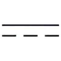 | Name: Direct current. Form 1. Remarks: The shape of this symbol is defined as character 3/15 of IEC 61286 “DIRECT CURRENT SYMBOL FORM TWO”, equivalent to UCS 2393 (Table 63) of ISO/IEC 10646 “DIRECT CURRENT SYMBOL FORM TWO”, according to IEC 61286. Source: IEC 60617-2019, IEEE Std 315-1993 | A1, A2, A3 |
| DC | Name: Direct current. Form 2. Remarks: Note that “DC” (written with uppe-case letters, without any dots and language independant) is a letter symbol in accordance with IEC 61293. The estblished abbreviation, on the other hand, for “direct current” is “d.c.” (with lower-case letters and dots). Source: IEC 60617-2019 | A2 |
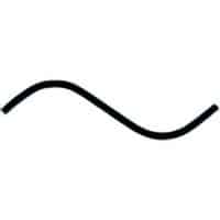 | Name: Alternating current. Form 1. Remarks: The shape of this symbol is defined as character 5/13 of IEC 61286 “ALTERNATING CURRENT SYMBOL LOW-FREQUENCY RANGE”, equivalent to UCS 2248 (Table 60) of ISO/IEC 10646 “TILDE OPERATOR” according to IEC 61286. Source: IEC 60617-2019, IEEE Std 315-1993 | A4, A5 |
| AC | Name: Alternating current. Form 2. Remarks: Note that “AC” (written with uppe-case letters, without any dots and language independant) is a letter symbol in accordance with IEC 61293. The estblished abbreviation, on the other hand, for “alternating current” is “a.c.” (with lower-case letters and dots). Source: IEC 60617-2019 | A5 |
 | Name: Single-phase alternating current. Source: IEC 60417-2020 | A6 |
 | Name: Two-phase alternating current. Source: IEC 60417-2020 | A7 |
 | Name: Three-phase alternating current. Source: IEC 60417-2020 | A8 |
 | Name: Both direct and alternating current. Alternative name: Direct or alternating current (universal). Source: IEC 60417-2020 | A9 |
 | Name: Two-phase alternating current with neutral conductor. Source: IEC 60417-2020 | A10 |
 | Name: Three-phase alternating current with neutral conductor Source: IEC 60417-2020 | A11 |
 | Name: Alternating current (indication of frequency). Symbol restrictions: Shown for alternating current of 50 Hz. Source: IEC 60617-2019 | A12 |
 | Name: Alternating current (indication of frequency range: low). Alternative names: Different frequency ranges. Relatively low frequencies (power frequencies or sub-audio frequencies). Source: IEC 60617-2019 | A13 |
 | Name: Alternating current (indication of frequency range: medium). Alternative names: Different frequency ranges. Medium frequencies (audio). Source: IEC 60617-2019 | A13 |
 | Name: Alternating current (indication of frequency range: high). Alternative names: Different frequency ranges. Relatively high frequencies (super audio, carrier). Source: IEC 60617-2019 | A13 |
 | Name: Rectified current with alternating component. Remarks: If it is necessary to distinguish from a rectified and filtered current. Source: IEC 60617-2019 | – |
 | Name: DC to DC converter Source: IEC 60417-2020 Remark: Converting DC to DC | – |
 | Name: AC/DC-converter; rectifier; substitute power supply Source: IEC 60417-2020 | A14 |
 | Name: DC/AC-converter Source: IEC 60417-2020 | A15 |
 | Name: Pulse, alternating current Source: IEC 60617-2019 | A16 |
Application Notes
A1: To indicate on the rating plate that the equipment is suitable for direct current only; to identify relevant terminals.
A2: The voltage may be indicated at the right of the symbol and the type of system at the left.
Example – “Two conductors with mid-wire, 220/110 V”: 2/M 220/110 V or 2/M DC 220/110 V.
A3: For different unspecified frequency ranges see symbols , and .
A4: To indicate on the rating plate that the equipment is suitable for alternating current only; to identify relevant terminals.
A5: a) The numerical value of the frequency or the frequency range may be added at the right-hand side of the symbol.
Example – “Alternating current, 50 Hz”: 50 Hz or AC 50 Hz.
Example – “Alternating current, frequency range 100 kHz to 600 kHz”: 100 kHz … 600 kHz or AC 100 kHz … 600 kHz
b) The voltage value may also be indicated to the right of the symbol. The number of phases and the presence of a neutral may be indicated at the left-hand side of the symbol.
Example – “Alternating current: three-phase with neutral, 400 V (230 V between phase and neutral), 50 Hz”. (See also IEC 61293): 3/N 400/230 V 50 Hz or 3/N AC 400/230 V 50 Hz.
c) If it is necessary to indicate a system in accordance with the designations established in IEC 60364-1 the corresponding designation shall be added to the symbol.
Example – “Alternating current, three-phase, 50 Hz; system having one point directly earthconnected and separate neutral and protective conductors throughout”: 3/N/PE 50 Hz / TN-S or 3/N/PE AC 50 Hz / TN-S.
A6: To indicate on the rating plate that the equipment is suitable for single-phase alternating current only and to identify relevant terminals.
A7: To indicate on the rating plate that the equipment is suitable for two-phase alternating current only and to identify relevant terminals.
A8: To indicate on the rating plate that the equipment is suitable for three-phase alternating current only and to identify relevant terminals.
A9: To indicate on the rating plate that the equipment is suitable for both direct and alternating current (universal); to identify relevant terminals.
A10: To indicate on the rating plate that the equipment is suitable for two-phase alternating current with a neutral conductor only and to identify relevant terminals.
A11: To indicate on the rating plate that the equipment is suitable for three-phase alternating current with a neutral conductor only and to identify relevant terminals.
A12: The numerical value of the frequency or the frequency range may be added at the right-hand side of the symbol.
A13: Symbols , and may be used when it is necessary on a given drawing to distinguish between different frequency ranges.
A14: To identify an AC/DC-converter and, in case of plug-in devices, to identify the relevant receptacles.
A15: To identify a DC/AC-converter and its associated terminals and controls.
A16: Each symbol represents an idealized shape of the waveform.