Electric contact is a state of two conductive parts which touch each other intentionally or accidentally and form a single continuous conductive path [source: IEC 60050-151].
Types of Electrical Contacts
The following types of electrical contacts are defined:
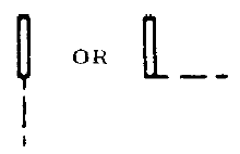
- Fixed contact for jack, key, relay, switch, etc:
 or
or 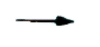
- Fixed contact with momentary contact (automatic return):

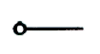
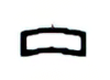
- Sleeve:
 . The broken line – — – indicates where line connection to a symbol is made and is not part of the symbol.
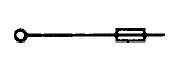
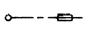
 - Adjustable or sliding contact for resistor, inductor, etc: or

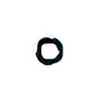
- Locking:

- Nonlocking:
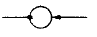
- Segment; bridging contact:
 or
or 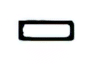
- Vibrator reed:
- Vibrator split reed:
- Rotating contact (slip ring) and brush:
Basic Contact Assemblies
The conventional approach for representing a contact involves utilizing a symbol that signifies the state of the circuit when the activating mechanism is in its deenergized or nonoperational state. The activating mechanism can be mechanical, electrical, or of another nature, and it might be necessary to include an explanatory note alongside the symbol to specify the precise moment at which the contact functions. This could encompass the point at which a contact either closes or opens in response to changes in pressure, level, flow, voltage, current, and similar factors. In situations where it is deemed beneficial to depict contacts in their energized or operational state, and to avoid any potential confusion, an elucidating note must be appended to the illustration.
Auxiliary switches or contacts for circuit breakers, etc, may be designated as follows:
a) Closed when device is energized or operated position.
b) Closed when device is in deenergized or nonoperated position.
– aa) Closed when operating mechanism of main device is in energized or operated position.
– bb) Closed when operated mechanism of main device is in deenergized or nonoperated position.
In the parallel-line contact symbols shown below, the length of the parallel lines shall be approximately 11/4 times the width of the gap.
Contact States
Closed Contact (Break)
A contact pair that is normally closed (NC) remains in a conductive state when it or the device controlling it is not energized or in a relaxed state.
Symbols: 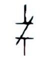 or
or 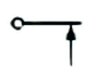 or
or 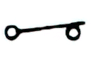 .
.
Open Contact (Make)
On the other hand, a contact pair that is normally open (NO) remains in a non-conductive state when it or the device operating it is not energized or in a relaxed state.
Symbols: 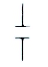 or
or 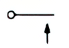 or
or 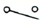 .
.
Break-Before-Make (Transfer)
Transfer (break-before-make) contact is a contact combination in which one contact opens its connection to another contact and then closes its connection to a third contact.
Symbols: 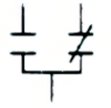 or
or 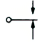 or
or ![]() .
.
Make-Before-Break (Continuity Transfer)
Continuity transfer (make-before-break) contact is a contact combination in which one contact closes connection to another contact and then opens its prior connection to a third contact.
Symbol:  .
.
Contact Form
The contact combinations used and their designations are shown in Figure 1 (according to the National Association of Relay Manufacturers and its successor, the Relay and Switch Industry Association).
| Form | Description | ANSI EIA RS-473 symbol |
| A | MAKE or SPST-NO (Form A contacts, normally open). A contact combination that is open when the armature is in its unoperated position. | 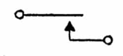 |
| B | BREAK or SPST-NC (Form B contacts, normally closed). Its operation is logically inverted from Form A. A contact combination which is closed when the armature is in its unoperated position. | 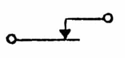 |
| C | BREAK, MAKE (TRANSFER). These terminals are usually labeled as normally open (NO), common (C), and normally closed (NC), i.e. (NO-C-NC). An alternate notation for Form C is SPDT. | 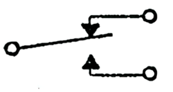 |
| D | MAKE, BREAK (CONTINUITY TRANSFER). If Form C ensures that both terminals are open for a short time, Form D ensures that all three terminals are closed for a short time. | 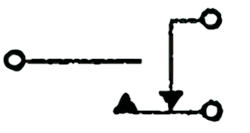 |
| E | BREAK, MAKE, BREAK or SPDT (B-M-B). | 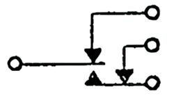 |
| F | MAKE, MAKE or SPST (M-M). | 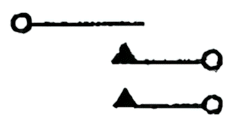 |
| G | BREAK, BREAK or SPST (B-B). | 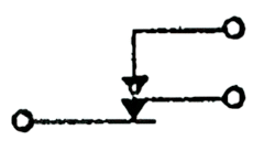 |
| H | BREAK, BREAK, MAKE or SPDT (B-B-M). | 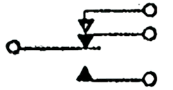 |
| I | MAKE, BREAK, MAKE or SPDT (M-B-M). | 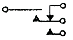 |
| J | MAKE, MAKE, BREAK or SPDT (M-M-B). | 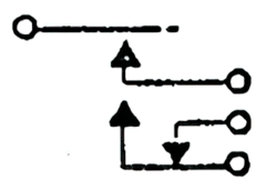 |
| K | SINGLE POLE DOUBLE THROW CENTER OFF or SPDT-NO. Form K contacts, also known as center-off contacts, exhibit a distinct dissimilarity from Form C contacts. They possess a unique characteristic wherein there exists a center-off or normally open position, where neither connection is established. While SPDT toggle switches often incorporate a center off position, relays with this particular configuration are relatively uncommon and less frequently encountered. | 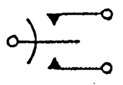 |
| L | BREAK, MAKE, MAKE or SPDT (B-M-M). | 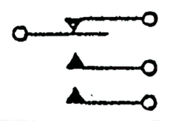 |
| U | DOUBLE MAKE CONTACT ON ARM. | 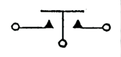 |
| V | DOUBLE BREAK CONTACT ON ARM. | 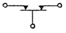 |
| W | DOUBLE BREAK, DOUBLE MAKE, CONTACT ON ARM. | 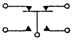 |
| X | DOUBLE MAKE. Contact, double make is a contact combination in which contacts on a single conductive support simultaneously close electrical circuits connected to the contact of two independent contacts providing two contact air gaps in series when the contact is open (sometimes called normally-open-double-break contact). Form X or double-make contacts can also be described as SPST-NO contacts. | 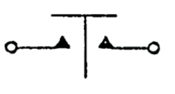 |
| Y | DOUBLE BREAK. Contact, double break is a contact combination in which contacts on a single conductive support simultaneously open electrical circuits connected to two independent contacts, providing two contact air gaps in series when the contact is open. Form Y or double-break contacts can also be described as SPST-NC contacts. | 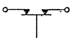 |
| Z | DOUBLE BREAK, DOUBLE MAKE. Form Z or double-make double-break contacts are similar to Form C contacts, but they typically feature four external connections: two for the normally open circuit and two for the normally closed circuit. Similar to forms X and Y, both current paths consist of two contacts connected in series, which are mechanically linked and controlled by a single actuator. This configuration is also referred to as an SPDT (Single Pole Double Throw) contact. |  |
References
- ANSI EIA RS-473
- IEEE Std 315