Electric motor is an electric machine intended to transform electric energy into mechanical energy.
This article provides my thoroughly researched overview of standardized electric motor symbols published in key normative documentation including IEC and IEEE standards. It represents the culmination of an exhaustive review of electric motor graphical symbols from these authoritative sources. The article includes both general symbols for electric motors as well as more specific symbols denoting various motor types and configurations like DC motors, AC motors, linear motors, stepping motors, and induction motors. Usage notes derived from careful analysis of the standards explain when certain symbols should be applied.
See also: Inductor Symbols ►
| Symbol | Description | Notes |
|---|---|---|
 | Name: Electric motor Source: IEC 60417-2020, IEEE Std 315-1993 | A1 |
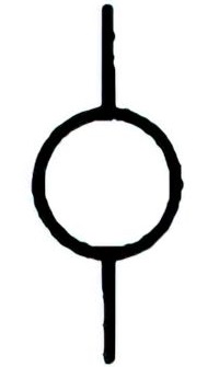 | Name: Armature of motor or rotating machine Source: IEEE Std 315-1993 | – |
 | Name: Operated by electric motor Source: ANSI/IEEE Std 315A-1986 | – |
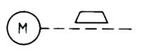
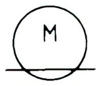
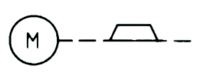 | Name: Brake, applied Alternative name: Electric motor with brake applied. Source: IEC 60617-2019, ANSI/IEEE Std 315A-1986 | – |
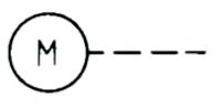
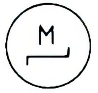
 | Name: Brake, released Alternative name: Electric motor with brake released Source: IEC 60617-2019, ANSI/IEEE Std 315A-1986 | – |
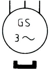
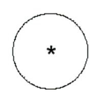 | Name: Machine, general symbol Alternative name: Rotary converter; Generator; Synchronous generator; Motor; Synchronous motor Source: IEC 60617-2019 | A2, A3, A4 |
 | Name: Linear motor, general symbol Source: IEC 60617-2019 | – |
 | Name: Stepping motor, general symbol Source: IEC 60617-2019, ANSI/IEEE Std 315A-1986 | – |
 | Name: Series motor, DC Source: IEC 60617-2019 | A3 |
 | Name: Shunt motor, DC Source: IEC 60617-2019 | A3 |
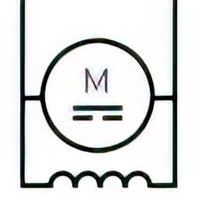
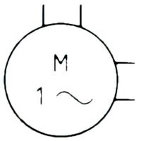
 | Name: Series motor, single-phase Source: IEC 60617-2019 | A3 |
 | Name: Repulsion motor, single-phase Source: IEC 60617-2019 | A3 |
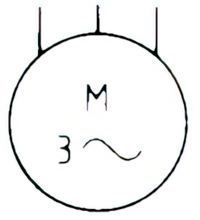
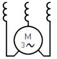 | Name: Series motor, three-phase Source: IEC 60617-2019 | A3 |
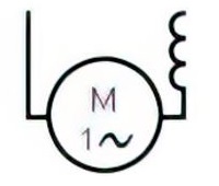
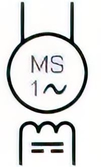 | Name: Synchronous motor, single-phase Source: IEC 60617-2019 | A3 |
 | Name: Induction motor, three-phase, squirrel cage Source: IEC 60617-2019, ANSI/IEEE Std 315A-1986 | A3, A5 |
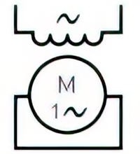
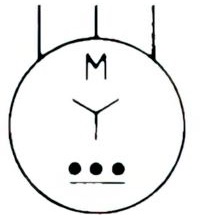
 | Name: Induction motor, single-phase, squirrel-cage Remark: Ends of split-phase winding brought out. Source: IEC 60617-2019, ANSI/IEEE Std 315A-1986 | A3, A5 |
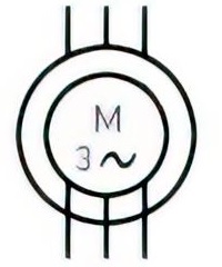 | Name: Induction motor, three-phase, with wound rotor Source: IEC 60617-2019 | A3, A5 |
 | Name: Induction motor, three-phase, star-connected Remark: With built-in automatic starter Source: IEC 60617-2019, ANSI/IEEE Std 315A-1986 | A3, A5 |
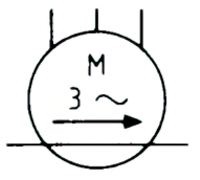 | Name: Linear induction motor, three-phase Remark: Movement only in one direction Source: IEC 60617-2019 | A3, A5 |
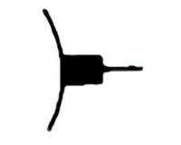 | Name: Electric motor brush Source: IEC 60617-2019, ANSI/IEEE Std 315A-1986 | A6 |
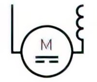
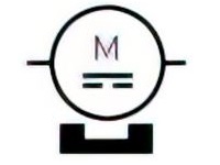 | Name: Permanent magnet DC motor Source: IEC 60617-2019 | – |
 | Name: Synchronous generator, three-phase with permanent magnet Source: IEC 60617-2019, ANSI/IEEE Std 315A-1986 | A3 |
Application Notes
A1:
To identify the piece of equipment that operates by use of electricity and is used to produce additional power.
A2:
The asterisk, *, shall be replaced by one of the following letter designations:
- C Rotary converter
- G Generator
- GP Permanent magnet generator
- GS Synchronous generator
- M Motor
- MG Machine capable of use as a generator or motor
- MGS Synchronous generator – motor
- MP Permanent magnet motor
- MS Synchronous motor
- RC Rotary Condenser
A3:
The symbols  and
and  may be added, as shown in many of the examples.
A4:
For static power generators, see symbol  and the examples of that.
A5:
The general symbol for a machine should be used to represent an asynchronous machine, if no external connections to the rotor exist, for example in a squirrel cage motor. An inner circle, representing the rotor, should be shown in those cases where external connections to the rotor exist, see for example symbol .
A6:
Brushes are shown only if necessary. For an example of application, see symbol 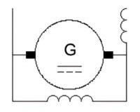 .
.