Transformer is an electric energy converter without moving parts that changes voltages and currents associated with electric energy without change of frequency.
Transformer symbols are graphical representations used in electrical circuit diagrams to denote different types of transformers. Single line transformer symbols show windings and core with a simple circle. More detailed symbols use reactor symbols to depict windings, taps, and polarity. Standard symbols include autotransformer, current, voltage, and three-phase types showing winding connections and functionality. Instantaneous voltage polarities and fail-safe operations may also be portrayed.
See also: Choke / Coil / Inductor Symbols ►
General Symbols
| Symbol | Description | Notes |
|---|---|---|
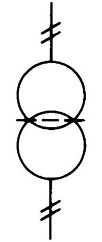
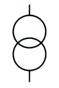
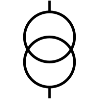 | Name: Transformer with two windings, general symbol. Form 1. Source: IEC 60617-2019, IEC 60417-2020, IEEE Std 315-1993 | A1, A2, A3 |
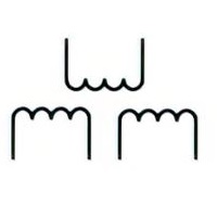
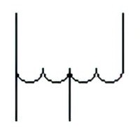
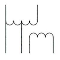
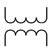 | Name: Transformer with two windings, general symbol. Form 2. Source: IEC 60617-2019 | A1, A2, A4, A5 |
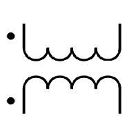 | Name: Transformer with two windings (and instantaneous voltage polarity indicators). Form 2. Remarks: Instantaneous currents entering the marked ends of the windings produce aiding fluxes. Source: IEC 60617-2019 | A2, A5 |
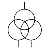 | Name: Transformer with three windings, general symbol. Form 1. Source: IEC 60617-2019, IEEE Std 315-1993 | A1, A2 |
 | Name: Transformer with three windings, general symbol. Form 2. Source: IEC 60617-2019 | A1, A2, A4, A5 |
 | Name: Transformer with two windings and screen. Form 1. Source: IEC 60617-2019, IEEE Std 315-1993 | A1 |
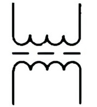 | Name: Transformer with two windings and screen. Form 2. Source: IEC 60617-2019, IEEE Std 315-1993 | A1, A4, A5 |
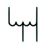
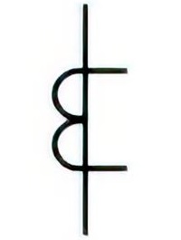
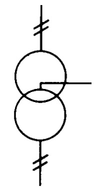 | Name: Transformer with centre tap on one winding. Form 1. Source: IEC 60617-2019, IEEE Std 315-1993 | A1 |
 | Name: Transformer with centre tap on one winding. Form 2. Source: IEC 60617-2019, IEEE Std 315-1993 | A1, A4, A5 |
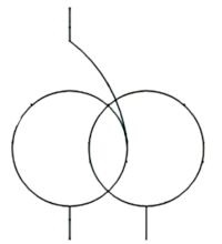
 | Name: Transformer with variable coupling. Form 1. Source: IEC 60617-2019, IEEE Std 315-1993 | A1 |
 | Name: Transformer with variable coupling. Form 2. Source: IEC 60617-2019 | A1, A4, A5 |
Autotransformer Symbols
| Symbol | Description | Notes |
|---|---|---|
 | Name: Autotransformer, general symbol. Form 1. | A1, A6 |
 | Name: Autotransformer, general symbol. Form 2. Source: IEC 60617-2019, IEEE Std 315-1993 | A1, A5 |
 | Name: Autotransformer, single-phase. Form 1. Source: IEC 60617-2019, IEEE Std 315-1993 | A1 |
 | Name: Autotransformer, single-phase. Form 2. Source: IEC 60617-2019, IEEE Std 315-1993 | A1, A4 |
 | Name: Autotransformer, three-phase, connection star. Form 1. Source: IEC 60617-2019, IEEE Std 315-1993 | A1 |
 | Name: Autotransformer, three-phase, connection star. Form 2. Source: IEC 60617-2019, IEEE Std 315-1993 | A1, A4, A5 |
 | Name: Autotransformer, single-phase with voltage regulation. Form 1. Source: IEC 60617-2019, IEEE Std 315-1993 | A1 |
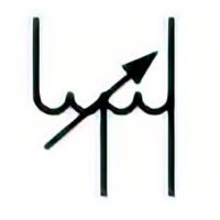 | Name: Autotransformer, single-phase with voltage regulation. Form 2. Source: IEC 60617-2019, IEEE Std 315-1993 | A1, A4 |
 | Name: Autotransformer with tertiary winding, general. Form 1. Source: IEC 60617-2019 | – |
 | Name: Autotransformer with tertiary winding, general. Form 2. Source: IEC 60617-2019 | – |
Current Transformer Symbols
| Symbol | Description | Notes |
|---|---|---|
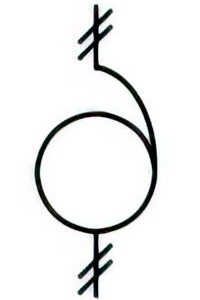
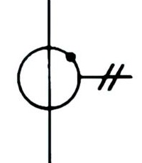
 | Name: Current transformer, general symbol. Form 1. Alternative name: Pulse transformer Source: IEC 60617-2019, IEEE Std 315-1993 | A1, A2 |
 | Name: Current transformer, general symbol. Form 2. Alternative name: Pulse transformer Source: IEC 60617-2019, IEEE Std 315-1993 | A1, A2, A4, A5 |
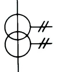
 | Name: Current transformer with two cores with one secondary winding on each core. Form 1. Remarks: The terminal symbols shown at each end of the primary circuit indicate that only a single device is represented. The terminal symbols may be omitted if terminal designations are used. Source: IEC 60617-2019, IEEE Std 315-1993 | A1, A2 |
 | Name: Current transformer with two cores with one secondary winding on each core. Form 2. Remarks: The terminal symbols shown at each end of the primary circuit indicate that only a single device is represented. The terminal symbols may be omitted if terminal designations are used. In form 2, core symbols may be omitted. Source: IEC 60617-2019, IEEE Std 315-1993 | A1, A2, A4, A5, |
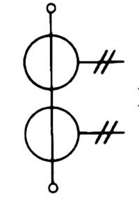
 | Name: Current transformer with two secondary windings on one core. Form 1. Source: IEC 60617-2019, IEEE Std 315-1993 | A1, A2 |
 | Name: Current transformer with two secondary windings on one core. Form 2. Remark: In form 2, the core symbol shall be drawn Source: IEC 60617-2019, IEEE Std 315-1993 | A1, A2, A4, A5 |
 | Name: Current transformer with one secondary winding with one tap. Form 1. Source: IEC 60617-2019, IEEE Std 315-1993 | A1, A2 |
 | Name: Current transformer with one secondary winding with one tap. Form 2. Source: IEC 60617-2019, IEEE Std 315-1993 | A1, A2, A4, A5 |
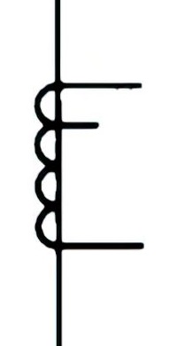
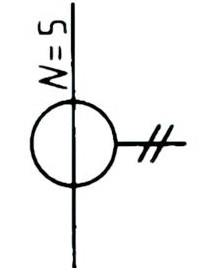 | Name: Current transformer with five passages of a conductor acting as a primary winding. Form 1. Remarks: This kind of current transformer has no built-in primary winding Source: IEC 60617-2019, IEEE Std 315-1993 | A1, A2 |
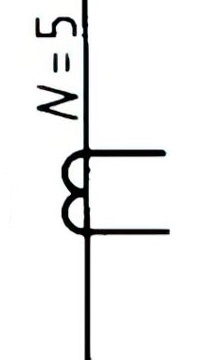 | Name: Current transformer with five passages of a conductor acting as a primary winding. Form 2. Remarks: This kind of current transformer has no built-in primary winding Source: IEC 60617-2019, IEEE Std 315-1993 | A1, A2, A4, A5 |
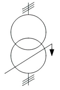
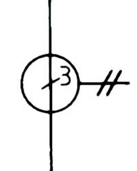 | Name: Pulse or current transformer with three threaded primary conductors. Form 1. Source: IEC 60617-2019, IEEE Std 315-1993 | A1, A2 |
 | Name: Pulse or current transformer with three threaded primary conductors. Form 2. Source: IEC 60617-2019, IEEE Std 315-1993 | A1, A2, A4, A5 |
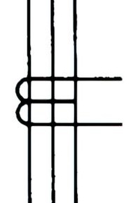
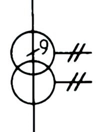 | Name: Pulse or current transformer with two secondary windings on the same core. Form 1. Remark: Shown with nine threaded primary conductors Source: IEC 60617-2019, IEEE Std 315-1993 | A1, A2 |
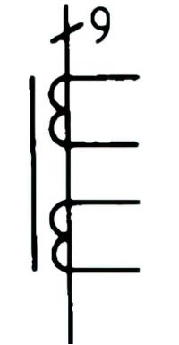 | Name: Pulse or current transformer with two secondary windings on the same core. Form 2. Remark: Shown with nine threaded primary conductors Source: IEC 60617-2019, IEEE Std 315-1993 | A1, A2, A4, A5 |
 | Name: Bushing type current transformer. Form 1. Source: IEC 60617-2019 | A1 |
 | Name: Bushing type current transformer. Form 2. Source: IEC 60617-2019 | A1 |
Voltage Transformer Symbols
| Symbol | Description | Notes |
|---|---|---|
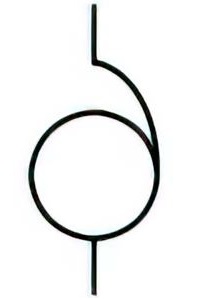
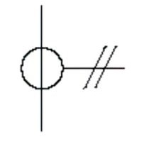
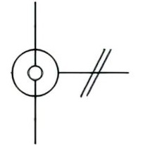
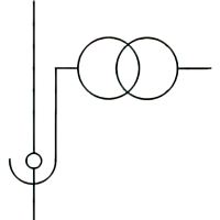
 | Name: Voltage transformer. Form 1. Alternative name: Measuring transformer Source: IEC 60617-2019, IEEE Std 315-1993 | A1 |
 | Name: Voltage transformer. Form 2. Alternative name: Measuring transformer Source: IEC 60617-2019, IEEE Std 315-1993 | A1, A4, A5 |
 | Name: Bushing type voltage transformer. Form 1 Source: IEC 60617-2019 | – |
 | Name: Bushing type voltage transformer. Form 2 Source: IEC 60617-2019 | A1 |
Symbols of Three-Phase Transformers
| Symbol | Description | Notes |
|---|---|---|
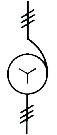
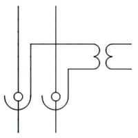
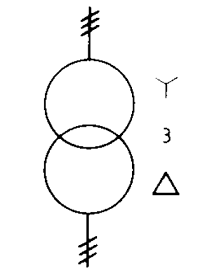
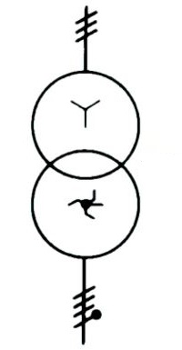
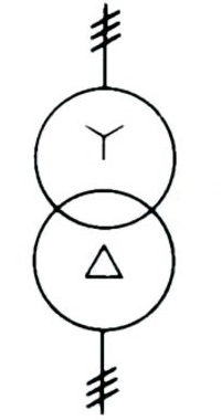 | Name: Three-phase transformer, connection star-delta. Form 1. Source: IEC 60617-2019 | A1 |
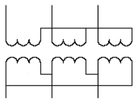
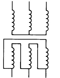 | Name: Three-phase transformer, connection star-delta. Form 2. Source: IEC 60617-2019 | A1, A4, A5 |
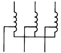
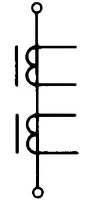
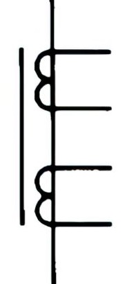
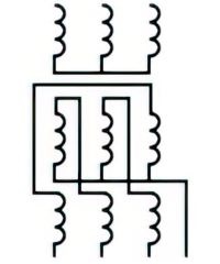
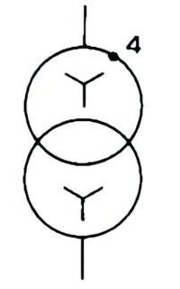 | Name: Three-phase transformer with four taps, connection: star-star. Form 1. Remarks: Each primary winding is shown with four available connection points in addition to those at the winding-ends. Source: IEC 60617-2019, IEEE Std 315-1993 | A1 |
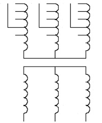 | Name: Three-phase transformer with four taps, connection: star-star. Form 2. Remarks: Each primary winding is shown with four available connection points in addition to those at the winding-ends. Source: IEC 60617-2019, IEEE Std 315-1993 | A1, A4, A5 |
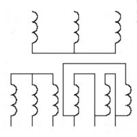
 | Name: Three-phase bank of single-phase transformers, connection star-delta. Form 1. Source: IEC 60617-2019, IEEE Std 315-1993 | A1 |
 | Name: Three-phase bank of single-phase transformers, connection star-delta. Form 2. Source: IEC 60617-2019, IEEE Std 315-1993 | A1, A4, A5 |
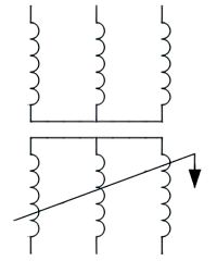
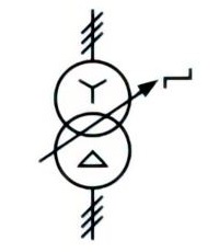 | Name: Three-phase transformer with tap changer. Form 1. Remark: On-load tap changer, connection star-delta. Source: IEC 60617-2019, IEEE Std 315-1993 | A1 |
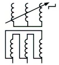 | Name: Three-phase transformer with tap changer. Form 2. Remark: On-load tap changer, connection star-delta. Source: IEC 60617-2019, IEEE Std 315-1993 | A1, A4, A5 |
 | Name: Three-phase transformer, connection star-zigzag with the neutral brought out. Form 1. Source: IEC 60617-2019, IEEE Std 315-1993 | A1 |
 | Name: Three-phase transformer, connection star-zigzag with the neutral brought out. Form 2. Source: IEC 60617-2019, IEEE Std 315-1993 | A1, A4, A5 |
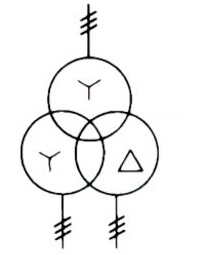 | Name: Three-phase transformer, connection star-star-delta. Form 1. Source: IEC 60617-2019, IEEE Std 315-1993 | A1 |
 | Name: Three-phase transformer, connection star-star-delta. Form 2. Source: IEC 60617-2019, IEEE Std 315-1993 | A1, A4, A5 |
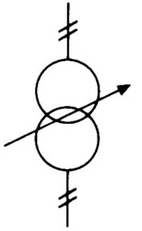
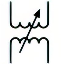
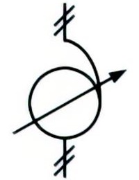
 | Name: Phase-shifting transformer, three-phase. Form 1. Source: IEC 60617-2019, IEEE Std 315-19 | A1 |
 | Name: Phase-shifting transformer, three-phase. Form 2. Source: IEC 60617-2019, IEEE Std 315-19 | A1 |
Application Notes
A1:
Two forms of symbols are given for the same type of transformer:
- Form 1 uses a circle to represent each winding. Its use is preferably restricted to single-line representation. Symbols for transformer cores are not used with this form.
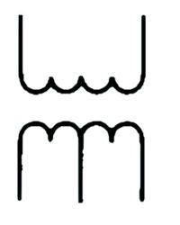
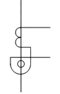
- Form 2 uses symbol
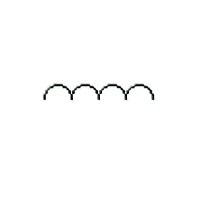 to represent each winding. The number of half-circles may be varied to differentiate between winding.
A2:
In the case of symbols for current and pulse transformers, straight lines, representing primary windings may be used for form 1 and form 2.
A3:
To identify switches, controls, connectors or terminals which connect electrical equipment to the mains through a transformer. It can also be used on an envelope or a case to indicate that it contains a transformer (e.g. in the case of a plug-in device).
A4:
If it is desired to show that there is a magnetic core, a single line may be added parallel to the symbol. The line may be annotated to indicate non-magnetic materials; it may be interrupted to indicate a gap in the core.
A5:
The instantaneous voltage polarities may be indicated in form 2 of the symbol. IEC 60375 gives a method of indicating the instantaneous voltage polarities of coupled electric circuits. For an example, see .
A6:
To indicate a fail-safe function, the letter F may be used adjacent of the symbol.; Published in: 3C/945/FDIS.