Identifying the electrical polarity of wires and connections is of great importance to any electrician. This guide gives a synopsis of the regularly used polarity representations included in electrical layouts and diagrams. Whether it is AC main wiring, DC circuits, or the two, these visible signs help electricians accurately determine live wires and stop any costly mistakes. The table below offers a fast breakdown of standard polarity symbols to be aware of when performing work with electric systems.
| Symbol | Description | Application notes |
|---|---|---|
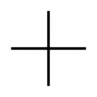 | Name: Plus; positive polarity Source: IEC 60617-2019 | To identify the positive terminal(s) of equipment which is used with, or generates direct current |
 | Name: Minus; negative polarity Source: IEC 60617-2019 | To identify the negative terminal(s) of equipment which is used with, or generates direct current. |
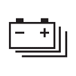
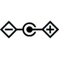 | Name: Polarity of DC power connector Source: IEC 60417-2020 | To identify the positive and negative connections (the polarity) of a DC power supply, or the positive and negative connections on a piece of equipment to which a DC power supply may be connected. |
Examples of Polarity Symbols Application
| Symbol | Description |
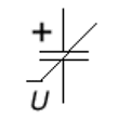 | Capacitor, voltage dependent and polarised |
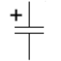 | Capacitor, polarized |
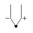 | Thermocouple |
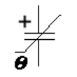 | Capacitor, temperature dependent and polarised |
 | State of charge, propulsion battery |
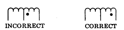
Instantaneous Polarity Markings
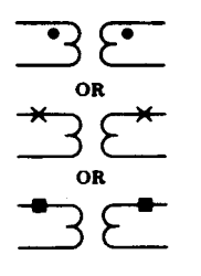
These polarity marks shall be used only when it is necessary to show the relative polarity of the windings.
- A — Instantaneous polarity of voltage across windings corresponds at points indicated by polarity marks. Instantaneous direction of current into (or out of) one polarity mark corresponds to current out of (or into) the other polarity mark. If instantaneous currents enter the windings at the marked points, they will produce aiding fluxes.
- B — The polarity marks shall be placed near one end of each coil or winding symbol. The exact location is immaterial as long as they are unambiguously placed, especially where other windings are drawn nearby. There shall be only one polarity mark per winding, even if the winding is tapped. The following is NOT permitted:
Application – instantaneous polarity markings with current transformer shown:
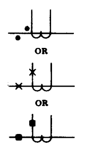
Application – instantaneous polarity markings with potential transformer shown: