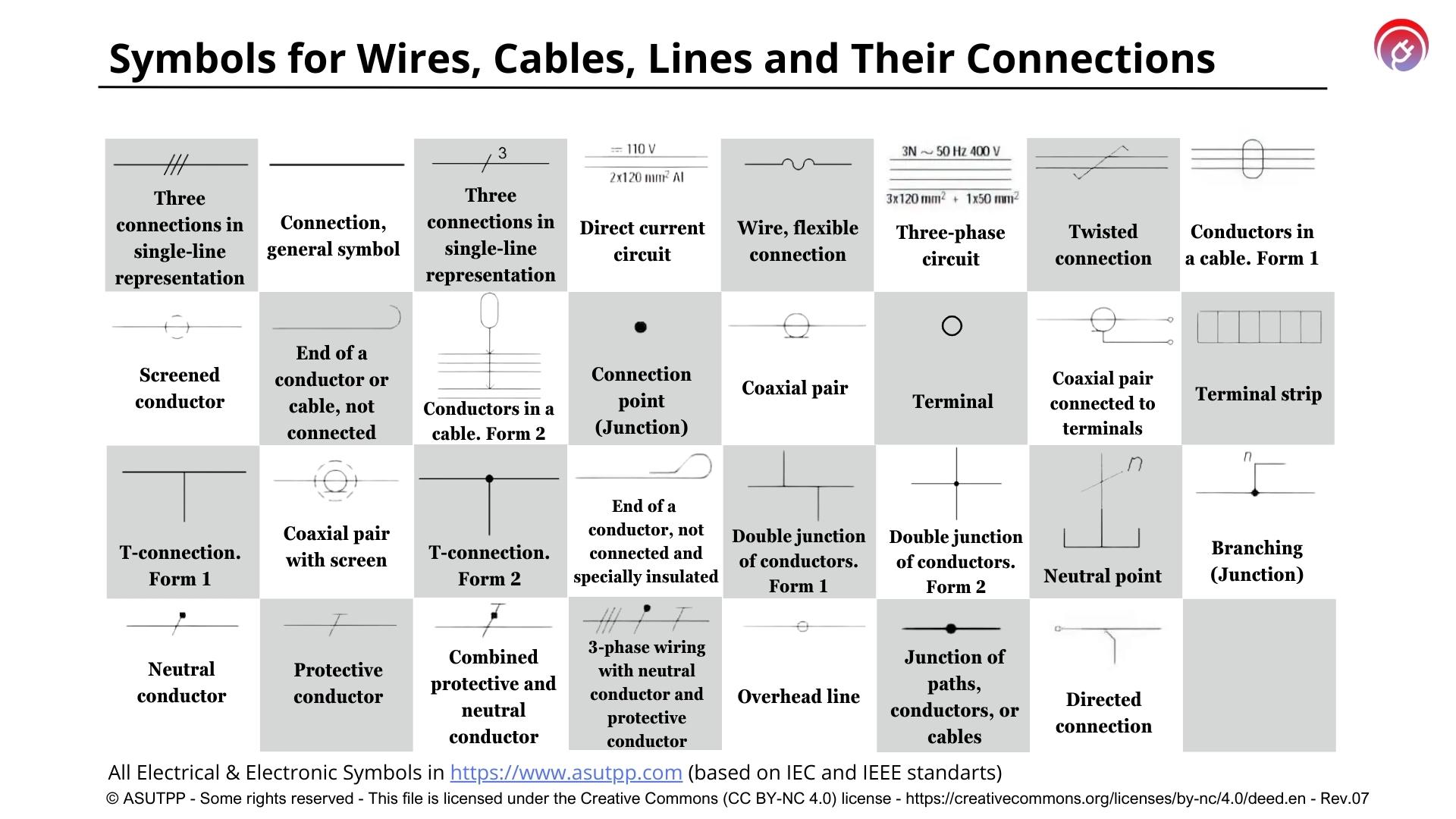
This table with symbols for wires, cables, lines and their connections was created by me after studying the relevant normative documentation – IEC and IEEE.
| Symbol | Description | Notes |
|---|---|---|
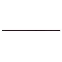 | Name: Connection, general symbol. Alternative names: – Conductive path or conductor; wire – Electric line / cable / Wire – Conductor of a single thread Source: IEC 60617-2019, IEEE Std 315-1993 | A1, A2, A3 |
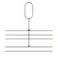
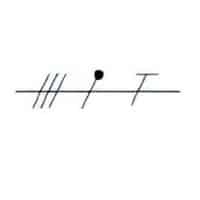
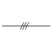 | Name: Group of connections (number of connections indicated). Form 1. Alternative name: Three connections in single-line representation Remark: Three connections shown. Source: IEC 60617-2019 | A2, A3, A4 |
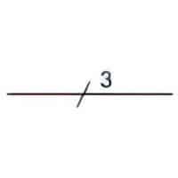 | Name: Group of connections (number of connections indicated). Form 2. Alternative name: Three connections in single-line representation. Remark: Three connections shown. Source: IEC 60617-2019 | A2, A3, A4 |
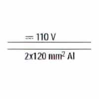 | Name: Direct current circuit. Remark: 110 V, two aluminium conductors of 120 mm2 Source: IEC 60617-2019 | A2, A3 |
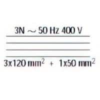 | Name: Three-phase circuit. Remarks: 50 Hz, 400 V, three conductors of 120 mm2 , with neutral of 50 mm2. 3N may be replaced by 3+N. Source: IEC 60617-2019 | A2, A3 |
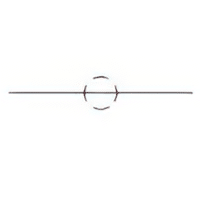
 | Name: Wire, flexible connection. Source: IEC 60617-2019 | – |
 | Name: Screened conductor. Alternative names: – Shielded wire – Shielded single conductor Source: IEC 60617-2019, IEEE Std 315-1993 | A5 |
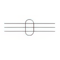 | Name: Conductors in a cable. Form 1. Remark: Three conductors shown. Source: IEC 60617-2019, IEEE Std 315-1993 | A5 |
 | Name: Conductors in a cable. Form 2. Remark: Five conductors, two of which marked by arrowheads are in one cable. Source: IEC 60617-2019 | A5 |
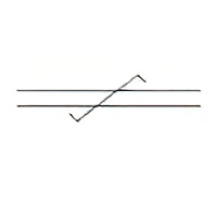 | Name: Twisted connection. Alternative name: Twisted wires. Remark: Two connections shown. Source: IEC 60617-2019, IEEE Std 315-1993 | A5 |
 | Name: Coaxial pair. Alternative name: Coaxial cable. Source: IEC 60617-2019 | A6 |
 | Name: Coaxial pair connected to terminals. Alternative name: Coaxial cable with terminals connected. Source: IEC 60617-2019 | A6 |
 | Name: Coaxial pair with screen. Alternative name: Coaxial cable with screen. Source: IEC 60617-2019 | – |
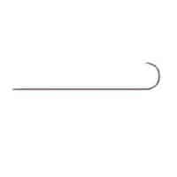 | Name: End of a conductor or cable, not connected. Source: IEC 60617-2019 | – |
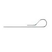 | Name: End of a conductor or cable, not connected and specially insulated. Source: IEC 60617-2019 | – |
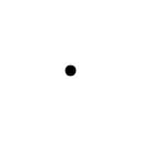 | Name: Connection point. Alternative name: Junction. Source: IEC 60617-2019, IEEE Std 315-1993 | – |
 | Name: Terminal. Source: IEC 60617-2019, IEEE Std 315-1993 | – |
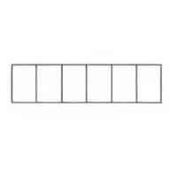 | Name: Terminal strip. Source: IEC 60617-2019 | A7 |
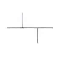
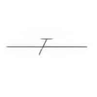
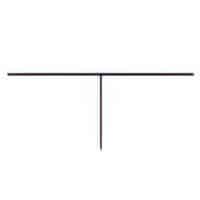 | Name: T-connection. Form 1. Alternative name: T-joint of functional connections. Source: IEC 60617-2019, IEC 60417-2020 | – |
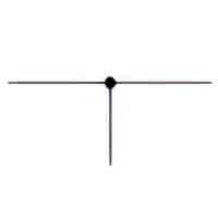 | Name: T-connection. Form 2. Remark: Shown with junction symbol. Source: IEC 60617-2019, IEC 60417-2020 | – |
 | Name: Double junction of conductors. Form 1. Source: IEC 60617-2019, IEC 60417-2020 | – |
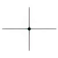 | Name: Double junction of conductors. Form 2. Alternative name: Joint of multiple functional connections. Source: IEC 60617-2019, IEC 60417-2020 | – |
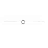
 | Name: Branching. Alternative name: Junction. Remark: Junction common to a group of identical and repeated parallel circuits. Source: IEC 60617-2019 | A8 |
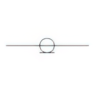
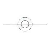
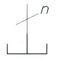 | Name: Neutral point. Remark: Point at which multiple conductors are connected together to form the neutral point in a multiphase system. Source: IEC 60617-2019 | A8, A9 |
 | Name: Neutral conductor. Alternative name: Neutral wire. Source: IEC 60617-2019 | A10 |
 | Name: Protective conductor. Alternative name: Protective wire. Source: IEC 60617-2019 | A10 |
 | Name: Combined protective and neutral conductor. Source: IEC 60617-2019 | A10 |
 | Name: Three-phase wiring with neutral conductor and protective conductor. Source: IEC 60617-2019 | A10 |
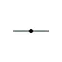 | Name: Junction of paths, conductors, or cables. Remark: If desired, indicate path type, or size. Source: IEEE Std 315-1993 | – |
 | Name: Overhead line Source: IEC 60617-2019 | – |
| Name: Group of connections. Remark: See also symbol “Connection, general”. Source: IEC 60617-2019 | A2, A3, A4 |
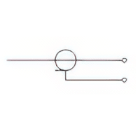
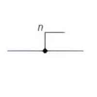
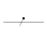
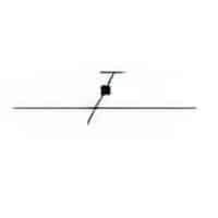
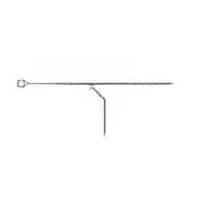 | Name: Directed connection. Symbol restrictions: This symbol shall not be used if there is no electrical connection, e.g. at bundling. Remark: The slanting line shall point in the direction of the the connection point. The symbol is shown with a conductor coming from the right side going to the left side, with a connection going to the bottom through a connection point situated to the left. Source: IEC 60617-2019 | A4, A9, A11 |
Application Notes
A1: A single line represents the entire group of conductors or the transmission path needed to guide the power or signal.
A2: Additional information may be indicated such as:
- kind of current
- system of distribution
- frequency
- voltage
- number of conductors
- cross-sectional area of each conductor
- the chemical symbol for the conductor material
The number of conductors is followed by the sectional area, separated by x.
If different sizes are used, their particulars should be separated by +.
For dimensional data:
- for low-frequency cables and wires, see IEC 60189 (series); and
- for multicore and symmetrical pair/quad cables for digital communications, see IEC 61156-1;
- for radio-frequency cables, see IEC 61196 (series)
- for optical fibres, see IEC 60793-1 (Series) , IEC 60793-2 (series) and ITU specifications for optical fibres.
A3: The length of the symbol for connection, or group of connections, may be adjusted to the layout of the diagram.
A4: If a single line represents a group of conductors, the number of connections may be indicated either by adding as many oblique strokes or one stroke followed by the figure for the number of connections.
A5: A drawing method in which the symbol for conductors in a cable , screened conductor , or twisted connection is shown either above, below, or beside the intermingled group of conductor symbols may be used if several conductors are contained within the same screen or cable or are twisted together, but the symbols for these conductors are intermingled with symbols for other connections.
The symbol shall be connected by a leader line pointing to the individual lines representing the conductors within the same screen, cable or twisted group.
For an example, see .
A6: If the coaxial structure is not maintained, the tangential line shall be drawn only on the coaxial side.
A7: Terminal markings may be added.
A8: “n” shall be replaced by the total number of circuits. The figure shall be placed adjacent to the junction symbol. See IEC 61082-1.
A pair of mirror-imaged symbols indicates the extent of the circuit(s).
Illustration of concept: 10 parallel and identical resistors, see 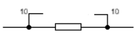 .
.
A9: Dotted lines are used to indicate the context of the actually described symbol in order to facilitate the understanding and application of it.
At the application of the symbol such lines are to be replaced by other types of lines in accordance with applicable rules for the preparation of diagrams.
A10: The symbols , , , may be replaced by letter symbols given in IEC 60445.
A11: Symbol is used if it is not necessary to specify in which end of the horizontal connecting line the physical connection is made to the line coming from below.
Symbol is used if it is required to explicitely specify in which end of the horzontal connecting line the physical connection is made to the line coming from below.