Capacitor is a two-terminal device characterized essentially by its capacitance.
This article provides a detailed list of capacitor symbols. This list is based on IEC and IEEE standards and contains pictograms and descriptions for the following capacitors: polarized, adjustable or variable, differential, shielded, split-stator, etc.
See also: relay symbols ►
| Symbol | Description | Notes |
|---|---|---|
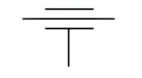
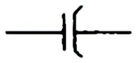
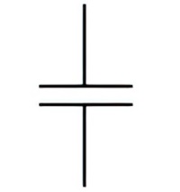 | Name: Capacitor, general symbol. Form 1. Source: IEC 60617-2019, IEEE Std 315-1993 | A1 |
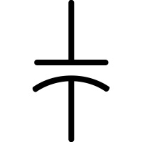 | Name: Capacitor, general symbol. Form 2. Source: IEEE Std 315-1993 | A1 |
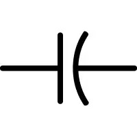
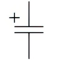 | Name: Capacitor, polarized. Form 1. Alternative name: Electrolytic capacitor Source: IEC 60617-2019, IEEE Std 315-1993 | – |
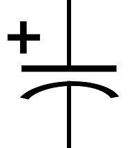 | Name: Capacitor, polarized. Form 2. Alternative name: Electrolytic capacitor Source: IEEE Std 315-1993 | – |
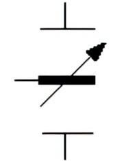
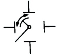
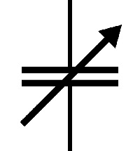 | Name: Capacitor, adjustable Alternative name: Capacitor with moving element indicated Source: IEC 60617-2019, IEEE Std 315-1993 | A2 |
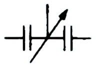
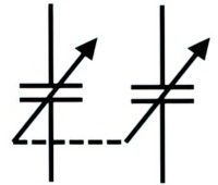 | Name: Adjustable or variable capacitors with mechanical linkage of units Source: IEEE Std 315-1993 | – |
 | Name: Capacitor, differential Alternative name: Continuously adjustable or variable differential capacitor Source: IEC 60617-2019, IEEE Std 315-1993 | – |
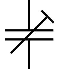 | Name: Capacitor with pre-set adjustment Source: IEC 60617-2019, ANSI/IEEE Std 315A-1986, IEEE Std 315-1993 | – |
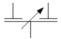
 | Name: Capacitor, split and adjustable Source: IEC 60617-2019 | – |
 | Name: Split-stator capacitor Remark: The capacitances of both parts increase or decrease simultaneously Source: IEEE Std 315-1993 | – |
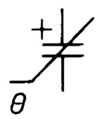 | Name: Capacitor, temperature dependent and polarised Alternative name: Ceramic capacitor Source: IEC 60617-2019, ANSI/IEEE Std 315A-1986 | A3 |
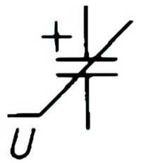 | Name: Capacitor, voltage dependent and polarised Alternative name: Semiconductor capacitor Source: IEC 60617-2019, ANSI/IEEE Std 315A-1986 | A4 |
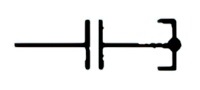
 | Name: Capacitor, lead-through Alternative name: Feed-through capacitor Source: IEC 60617-2019, ANSI/IEEE Std 315A-1986 | A5 |
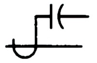
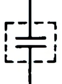 | Name: Shielded capacitor Source: IEEE Std 315-1993 | – |
 | Name: Phase-shifter capacitor Source: IEEE Std 315-1993 | – |
 | Name: Series capacitor and path open Source: IEEE Std 315-1993 | A6 |
 | Name: Series capacitor and path short-circuited Source: IEEE Std 315-1993 | A6 |
 | Name: Shunt capacitor Source: IEEE Std 315-1993 | – |
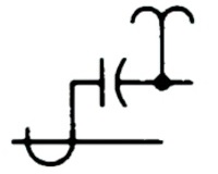
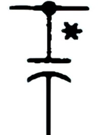 | Name: Coupling capacitor (for power-line carrier) Source: IEEE Std 315-1993 | A7 |
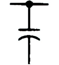
 | Name: Capacitor bushing for circuit breaker or transformer Source: IEEE Std 315-1993 | – |
 | Name: Capacitor-bushing potential device Source: IEEE Std 315-1993 | – |
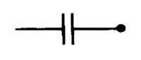
 | Name: Capacitor with identified electrode. Form 1. Source: IEEE Std 315-1993 | A8 |
 | Name: Capacitor with identified electrode. Form 2. Source: IEEE Std 315-1993 | A8 |
Symbols of capacitors
Application Notes
A1:
In accordance with IEEE Std 315-1993, capacitors may be represented by either of two methods. For convenience in referring to the capacitor symbols in this section, they are classified as follows:
- Form 1 symbols are drawn with two parallel lines;
- Form 2 symbols are drawn with one straight and one curved line.
The distance between the plates shall be between one-fifth and one-third of the length of a plate.
A2:
In accordance with IEEE Std 315-1993, if it is desired to indicate the moving element, the common intersection of the moving element with the symbol for variability and the connecting line is marked with a dot. See 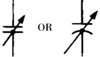
A3:
Temperature dependent polarized capacitor, where deliberate use is made of the temperature coefficient, for example, ceramic capacitor.
θ may be replaced by to t0.
A4:
Voltage dependent polarized capacitor, where deliberate use is made of the voltage dependent characteristic, for example, semiconductor capacitor.
U may be replaced by V.
A5:
Commonly used for bypassing high-frequency currents to chassis. For purposes of clarity, terminals may be shown on the feed-through element.
A6:
Commonly used on coaxial and wave-guide diagrams.
A7:
The asterisk is not part of the symbol. If specific identifications is desired, the asterisk is to be replaced by one of the following letter combinations:
- COM – Carrier communication
- LC – Carrier load control
- REL – Carrier relaying
- SUP – Carrier supervisory
- TLM – Carrier telemetering
- TT – Carrier transferred trip
A8:
For form 1, if it is necessary to identify the capacitor electrodes, the modified element shall represent the outside or lower potential electrode.
For form 2, if it is necessary to identify the capacitor electrodes, the curved element shall represent:
- a) The outside electrode in fixed paper-dielectric and ceramic-dielectric capacitors;
- b) The moving element in adjustable and variable capacitors;
- c) The low-potential element in feed-through capacitors.