MCB Trip Curves B, C and D: How to Read Them and Which to Use
On this page
The letter in front of the rating on a miniature circuit-breaker, the B in B16 or the C in C32, tells you how much current it takes to trip the breaker instantly. Everything else about the breaker can be identical. A B16 and a C16 carry the same 16 A forever, behave the same on a modest overload, and differ only in how they react to a sudden surge of several times their rating. That one difference decides whether a circuit trips every time a motor starts, and whether it disconnects fast enough under an earth fault.
The curves are defined in IEC 60898-1 (BS EN 60898-1 in the UK), the standard for circuit-breakers used in homes and similar installations.
Two mechanisms, one curve
An MCB has two tripping elements, and a time-current curve is simply both of them drawn on the same graph.
The thermal element is a bimetal strip heated by the load current. It handles overloads, so it is slow and its tripping time falls as the current rises. The magnetic element is a coil that pulls the trip mechanism when the current reaches a threshold. It handles short circuits and earth faults, and above its threshold it acts in a few milliseconds. The B, C and D curve types share essentially the same thermal behaviour and differ in where that magnetic threshold sits.
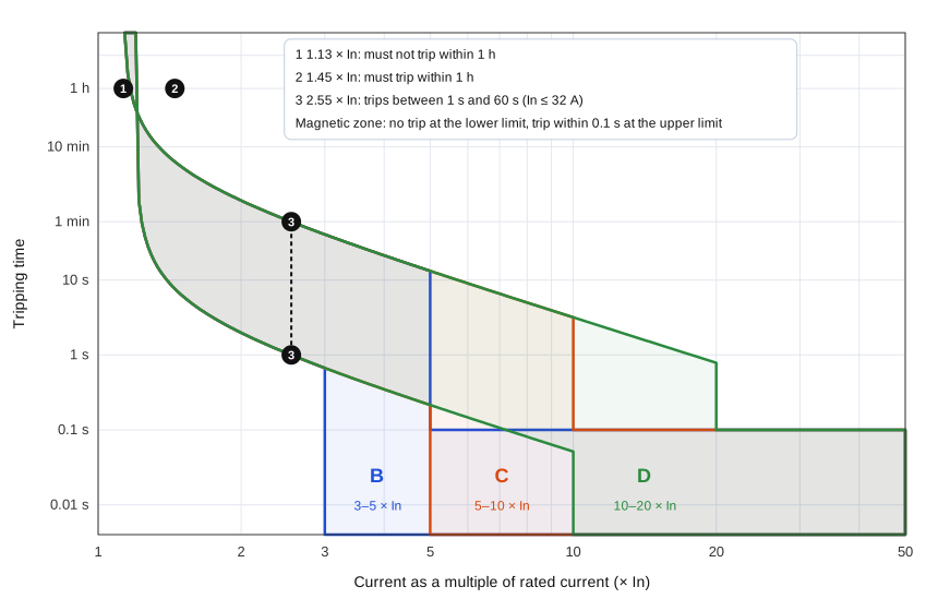
Reading the graph
Both axes are logarithmic. Along the bottom is the current as a multiple of the breaker’s rated current In; along the side is time. Each curve type is a band, not a line, because two breakers off the same production line will never trip at exactly the same instant. The standard fixes the edges of the band at a few test points:
- at 1.13 × In the breaker must not trip within one hour (two hours for ratings above 63 A);
- at 1.45 × In it must trip within one hour;
- at 2.55 × In it must trip in more than 1 s and less than 60 s for ratings up to 32 A, or less than 120 s above 32 A;
- at the lower limit of its magnetic range it must not trip in 0.1 s, and at the upper limit it must trip in less than 0.1 s.
The magnetic ranges are what the letters mean:
| Type | Instantaneous trip range | 16 A breaker trips instantly at |
|---|---|---|
| B | above 3 × In up to 5 × In | 48 to 80 A |
| C | above 5 × In up to 10 × In | 80 to 160 A |
| D | above 10 × In up to 20 × In | 160 to 320 A |
IEC 60898-1 allows the upper limit of type D to go as high as 50 × In for special applications. If you meet a D breaker in an old installation and the maximum earth fault loop impedance looks suspiciously generous, check the manufacturer’s data rather than assuming 20 × In.
Why the curve decides your maximum Zs
For automatic disconnection under an earth fault, the fault current has to reach the instantaneous trip level, because the thermal element is far too slow for the 0.4 s required on a 230 V final circuit. So the design calculation always uses the upper limit of the magnetic range: 5 × In for B, 10 × In for C, 20 × In for D.
The consequence is that a C breaker needs half the earth fault loop impedance of a B breaker of the same rating, and a D breaker needs a quarter. These are the maximum values from BS 7671 Table 41.3 for 230 V and a disconnection time of 0.4 s, including the 0.95 voltage factor:
| Rating | Type B | Type C | Type D |
|---|---|---|---|
| 6 A | 7.28 Ω | 3.64 Ω | 1.82 Ω |
| 10 A | 4.37 Ω | 2.19 Ω | 1.09 Ω |
| 16 A | 2.73 Ω | 1.37 Ω | 0.68 Ω |
| 20 A | 2.19 Ω | 1.09 Ω | 0.55 Ω |
| 32 A | 1.37 Ω | 0.68 Ω | 0.34 Ω |
Each figure is 230 V × 0.95 divided by the instantaneous trip current. For a C32: 218.5 ÷ 320 = 0.68 Ω. On a domestic TN-C-S supply with an external impedance of 0.35 Ω, that leaves only 0.33 Ω for the circuit itself, which a long radial in 4 mm² cable can easily exceed. That is the reason C breakers in houses so often end up behind an RCD that provides the disconnection instead.
Measured values on site are taken at ambient temperature, while the table assumes conductors at their operating temperature. The usual rule of thumb is to compare your reading with 80 % of the table value. The background is explained in TN-S earthing system and earth fault current.
Which curve for which load
Type B is the default for domestic lighting and socket circuits and for any resistive load: heaters, cookers, immersion heaters. It disconnects fastest under fault and allows the longest cable runs.
Type C is for loads with a significant switch-on surge. Small motors, compressors, fluorescent and HID lighting, and large groups of LED drivers fall into this category. An LED driver can draw an inrush of 30 to 100 times its running current for less than a millisecond while its input capacitor charges; ten of them switched together on one B10 will trip it on a cold morning. Driver datasheets usually state how many units a B or C breaker of a given rating can take.
Type D is for heavy inrush: transformers, welding sets, X-ray equipment, large motors started direct on line. It needs a low loop impedance, so it belongs close to the origin of the installation and on short, heavy cables.
When a B breaker keeps tripping at switch-on, changing it for a C of the same rating is a legitimate fix, but only after you have rechecked Zs for the new curve. Increasing the rating instead, B16 to B20 say, is not a fix at all if the cable was sized for 16 A.
K and Z curves
You will also meet K and Z characteristics on breakers built to IEC 60947-2, the standard for industrial circuit-breakers. Their thresholds are set by the manufacturer rather than by a fixed table, so always read the datasheet:
- K trips instantaneously at roughly 8 to 14 × In and has a tighter thermal characteristic. It is aimed at motors and transformers, where it rides through the starting current but protects the cable more closely on overload.
- Z trips at roughly 2 to 3 × In. It is used for semiconductor circuits, measuring circuits and long control cables where the fault current is low and a sensitive device is needed.
Selectivity is not guaranteed by the curve letter
A common assumption is that a C32 upstream of a B16 will always leave the C32 closed when the B16 clears a fault. It will on overload, and it will for small faults. But a solid short circuit close to the board can produce a fault current above the instantaneous threshold of both breakers, and then both trip together. Real selectivity between MCBs is limited and has to be read from the manufacturer’s selectivity tables. The topic is covered in circuit-breaker selectivity.
Short answers
Is a C-type breaker “stronger” than a B-type?
No. They carry the same continuous current. The C type only tolerates a bigger short surge before tripping instantly.
Can I replace a B32 with a C32 on a ring final circuit?
Only if the measured Zs is below the C32 limit of 0.68 Ω (about 0.55 Ω as a measured value) or the circuit is RCD protected and the RCD can provide the disconnection. On most domestic rings it is not, and there is rarely a reason to try.
Where is the curve letter printed?
On the front of the breaker, directly before the rating: B6, C20, D63. See how to read circuit-breaker markings for the rest of the label.
References
- IEC 60898-1, Circuit-breakers for overcurrent protection for household and similar installations.
- IEC 60947-2, Low-voltage switchgear and controlgear: circuit-breakers.
- BS 7671:2018+A2:2022, Table 41.3.