TN-S Earthing System: How It Works, Diagram, Pros and Cons
On this page
In a TN-S earthing system the supply has one point — normally the neutral point of the transformer — connected directly to Earth, and the installation’s exposed-conductive-parts are tied back to that same point through a protective conductor that stays separate from the neutral for the whole length of the system. IEC 60364-1 (clause 312.2.1) puts it in one line: a TN-S system is one “in which a separate protective conductor is used throughout the system”.
That single sentence explains both why TN-S behaves so predictably under fault and why networks stopped building it: it costs a fifth conductor from the substation to every customer.
What the letters T, N and S stand for
- T (first letter, from the French terre) — the source has a direct connection to Earth at one point.
- N (second letter) — the exposed-conductive-parts of the installation are connected to the earthed point of the source, not to an electrode of their own. That is what separates every TN arrangement from a TT system.
- S (third letter) — neutral and protective functions are carried by separate conductors, N and PE. Where one conductor does both jobs it is a PEN conductor and the letter becomes C, as in TN-C or TN-C-S.
The full family of codes is covered in our overview of the types of system earthing.
TN-S diagram
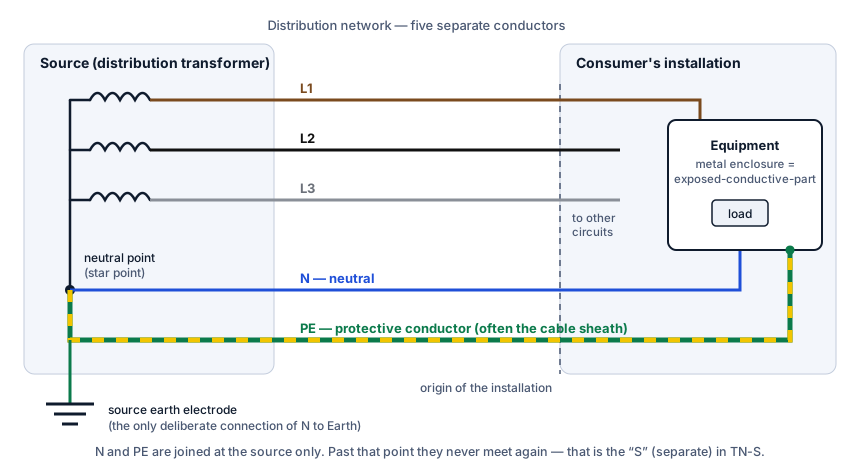
Read the drawing from left to right. The star point of the transformer secondary is connected to the source earth electrode. Two conductors leave that point: the neutral (blue), which carries load current, and the protective conductor (green-and-yellow), which carries current only when something has gone wrong. In many public networks the protective conductor is not a core at all but the lead sheath or steel armour of the service cable. At the installation the PE arrives at the main earthing terminal, and from there circuit protective conductors run to every exposed-conductive-part.
What happens when a line conductor touches the metalwork
Suppose the insulation fails inside the equipment on the right of the diagram and L1 contacts the enclosure. The fault current has a complete metallic loop to travel: out along L1, through the fault, back along the PE conductor to the star point. No soil is involved, so the loop impedance is low — typically well under one ohm — and the earth fault current is large, hundreds or thousands of amperes. A fuse or circuit-breaker sees that as a short circuit and opens.
The condition the designer has to prove is given in IEC 60364-4-41, clause 411.4.4:
Zs × Ia ≤ U0
where Zs is the earth fault loop impedance, Ia is the current that operates the protective device within the required time, and U0 is the nominal line-to-earth voltage. BS 7671 adds a minimum voltage factor Cmin of 0.95 to allow for the supply sitting at the bottom of its tolerance, so the UK form is Zs ≤ U0 × Cmin / Ia.
Worked example
A 32 A type B circuit-breaker to BS EN 60898 trips instantaneously at no more than five times its rating, so Ia = 5 × 32 = 160 A. With U0 = 230 V:
Zs ≤ 230 × 0.95 / 160 = 1.37 Ω
That is the figure printed in Table 41.3 of BS 7671 for a B32 device. If the external loop impedance measured at the origin is 0.8 Ω — the usual ceiling for a TN-S supply — the circuit conductors (line plus cpc, corrected for operating temperature) may contribute no more than 0.57 Ω before the circuit fails the check. While you have the cable length and size to hand, our voltage drop calculator covers the other check the same circuit has to pass.
The times that must be met in a 230 V TN system (Table 41.1) are 0.4 s for final circuits up to 63 A that include socket-outlets and up to 32 A that feed only fixed equipment, and 5 s for distribution circuits and anything larger. How a breaker’s curve translates into those times is explained in tripping time of a circuit-breaker.
How to recognise a TN-S supply
In the UK the tell-tale sign is at the service head. On a TN-S supply the earthing conductor of the installation is clamped, wiped or soldered onto the metallic sheath of the incoming cable, and it is visibly separate from the neutral. On a PME (TN-C-S) supply the earth comes out of the cut-out itself, from a terminal linked to the neutral block. A TT installation has neither: its earthing conductor disappears towards a rod outside.
Two cautions. First, appearance is a hint, not proof. Distribution networks have repaired and extended old sheathed cables with combined neutral-and-earth cable for decades, so a service that looks TN-S at the cut-out may be PME a few joints up the street. The distributor can confirm the declared arrangement. Second, the commonly quoted maximum external impedance for a TN-S supply, 0.8 Ω, is a declared ceiling and not a measurement. Ze has to be measured at the origin: lead sheaths corrode and joints loosen, and on a service that is fifty or sixty years old the real figure can sit well above the declared one.
TN-S compared with TN-C-S and TT
| TN-S | TN-C-S (PME) | TT | |
|---|---|---|---|
| Return path for an earth fault | Separate metallic PE back to the source | PEN conductor of the network, then separate PE in the installation | Installation electrode, the soil, source electrode |
| Typical declared Ze (UK) | up to 0.8 Ω | up to 0.35 Ω | set by the electrode; tens of ohms is normal |
| Usual fault protection | Overcurrent device | Overcurrent device | RCD |
| Effect of a broken supply neutral | Loss of supply or unbalanced voltages; metalwork stays at earth potential | Bonded metalwork can rise towards line voltage | Metalwork stays at earth potential |
| Cost to the network | Highest: an extra conductor everywhere | Lowest | Low; the electrode is the consumer’s |
The fourth row is the reason TN-S is still valued. In a PME system the protective conductor of the installation is connected to the supply neutral, so an open-circuit PEN upstream lifts every bonded pipe and enclosure above earth potential. In TN-S the PE has no such link: a lost neutral is a nuisance, not a shock hazard. That is why supplies to caravans and boats may not use a PME earth, and why outdoor vehicle-charging points on PME need open-PEN protection, while a true TN-S earth carries no such restrictions.
Where TN-S is still the right choice
Public networks rarely install it now, but inside the consumer’s boundary it is the normal arrangement. Anyone who owns the transformer — a factory, a hospital, a data centre — earths the star point once and runs five conductors from the main switchboard. Every installation fed from a PME supply is also TN-S downstream of the cut-out, which is what the hyphenated name TN-C-S means.
There is an electromagnetic reason as well. When neutral and protective functions share a conductor, part of the load current finds its way onto cable screens, building steel and pipework. IEC 60364-4-44 (clause 444.4.3) therefore advises against TN-C in buildings that house a significant amount of information technology equipment and recommends TN-S from the origin. The same logic applies to standby generators: the neutral is earthed at one point only, and N and PE stay apart everywhere else.
Points to check on a TN-S installation
- Main protective bonding is still required. A good supply earth does not remove the need to bond incoming metallic services and structural steel — see extraneous-conductive-parts. For a non-PME supply BS 7671 (544.1.1) sizes the main bonding conductor at not less than half the cross-sectional area of the earthing conductor, with a minimum of 6 mm² and no need to exceed 25 mm² in copper.
- Never reconnect N and PE downstream. A neutral-to-earth fault or a well-meant link in a sub-board turns part of the installation into TN-C, puts load current on the protective conductors and trips, or blinds, residual current devices.
- RCDs are still needed for additional protection. Regulation 411.3.3 asks for a 30 mA device on socket-outlets up to 32 A and on mobile equipment used outdoors, whatever the earthing system. The options are described in RCD types.
- Record the measured Ze and the prospective fault current at the origin. Both figures decide whether the devices chosen for the board will disconnect in time and can break the fault safely.
Common questions
Is TN-S safer than TN-C-S?
Under normal conditions both clear an earth fault in the same way and in the same time. The difference appears only when the supply neutral is lost: TN-S keeps the metalwork at earth potential and PME does not. For most buildings that risk is managed by bonding; for metal-clad structures outdoors, vehicles and boats it is the deciding factor.
Can I fit an earth rod to a TN-S installation?
An additional electrode connected to the main earthing terminal does no harm and is sometimes added for lightning protection or to back up an ageing cable sheath. It does not change the system type, and it is no substitute for a sound protective conductor: the rod’s resistance is far too high to operate a fuse or circuit-breaker.
My measured Ze is above 0.8 Ω. What now?
Tell the distributor, because the sheath or a joint is probably deteriorating and will get worse. Until it is repaired the circuits have to be re-checked against the measured value; if the loop impedances can no longer be met with overcurrent devices, RCD protection or conversion to TT are the usual remedies.
References
- IEC 60364-1:2005, clause 312.2 — types of system earthing.
- IEC 60364-4-41:2005+A1:2017, clause 411.4 — TN systems.
- IEC 60364-4-44:2007+A2:2018, clause 444 — measures against electromagnetic disturbances.
- IEC 60364-5-54:2011 — earthing arrangements and protective conductors.
- BS 7671:2018+A2:2022, Regulations 411.3, 411.4, 544.1 and Tables 41.1, 41.3.
This article explains the principles behind the standards; it does not replace them. Design, inspection and testing of an electrical installation must be carried out by a competent person against the edition of the regulations in force where the installation is located.