SPD Installation: Connection Types, Lead Length and Back-up Protection
On this page
A surge protective device is only as good as the way it is connected. The same Type 2 SPD that clamps a surge to 1.5 kV on the bench can let more than 2 kV through to the busbar if it hangs on a metre of cable looped around the inside of the enclosure. This guide covers the practical side: which connection type to use, where the device goes relative to the RCD, how long the leads may be, what size they should be and what protects the SPD itself.
For what an SPD is and the difference between Types 1, 2 and 3, start with what is a surge protective device and the complete SPD guide.
Connection types CT1 and CT2
IEC 60364-5-53 describes two ways of connecting SPDs between the live conductors and earth. You will see them in catalogues as “4+0” and “3+1” for a three-phase supply, or “2+0” and “1+1” for single-phase.
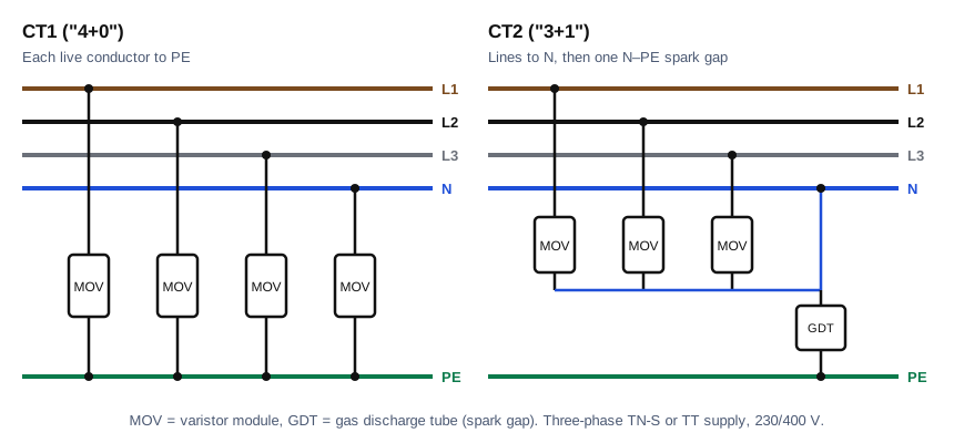
CT1 places a protective module between each live conductor and PE, the neutral included. It is the natural arrangement in a TN-S system and in the TN-S part of a TN-C-S installation, where neutral and PE are bonded at the origin and sit at almost the same potential.
CT2 places varistors from each line to neutral and then one heavy-duty spark gap, a gas discharge tube, from neutral to PE. Under normal conditions the spark gap does not conduct at all, so there is no leakage current from the live conductors to earth. That property is what makes CT2 the right answer in TT systems.
TT systems and the RCD
In a TT installation the SPD often has to sit on the supply side of the main RCD, because a surge current flowing through the RCD towards earth would trip it and might damage it. Put a CT1 device upstream of the RCD and you have a problem: a failed varistor between line and PE creates an earth fault that the RCD cannot see, because it is on the wrong side of it. The only remaining disconnection is the supply fuse, and with the earth fault loop impedance of a TT installation, often tens of ohms, that fuse will never blow. The SPD enclosure and everything bonded to the main earthing terminal could sit at a dangerous voltage indefinitely.
CT2 solves this. A failed line-to-neutral varistor is a line-to-neutral short circuit, which the upstream overcurrent device clears quickly, and the neutral-to-PE spark gap does not fail short in normal service. So in a TT installation:
- upstream of the RCD, use CT2 (3+1 or 1+1);
- downstream of the RCD, either type is possible, and if the RCD is in the path of the surge current, a time-delayed S-type RCD survives far better than a general-type one.
Lead length: the 0.5 m rule
Every metre of conductor has an inductance of roughly 1 µH. A surge current rises very fast, so even a short lead develops a large voltage of its own, and that voltage adds to the protection level Up of the SPD.
A worked example: a modest surge of 5 kA with an 8/20 µs waveform reaches its peak in 8 µs, a rate of rise of about 0.6 kA per microsecond. Across 1 µH that produces about 600 V. An SPD with Up = 1.5 kV connected with one metre of cable in total therefore delivers around 2.1 kV to the equipment it is protecting. Household equipment in overvoltage category II is designed to withstand 2.5 kV, and sensitive electronics in category I only 1.5 kV. The margin has gone.
That is why BS 7671 regulation 534.4.8 asks for the total length of the connecting conductors, line side plus earth side, to be kept as short as possible and preferably not more than 0.5 m. It must never exceed 1 m. Four practical ways to keep inside it:
- Mount the SPD close to the main switch or the incoming terminals and next to the earth bar, not wherever there happens to be a spare way.
- Run the line and PE conductors of the SPD together and keep them short, rather than letting them form a large loop.
- Where the board layout makes the leads long, use a Kelvin, or V-shape, connection: bring the incoming conductor to the SPD terminal first and continue from there to the busbar, so the lead inductance is no longer in series with the protected circuit. Check that the SPD terminals are rated for the load current before you do this.
- Prefer an SPD integrated in the consumer unit by the manufacturer, which has the leads designed in.
Conductor size
BS 7671 regulation 534.4.10 gives minimum cross-sections for the conductor between the SPD and the main earthing terminal or protective conductor: 4 mm² copper for a Type 2 SPD and 16 mm² copper for a Type 1 SPD. The line-side conductors are usually the same size, or as specified by the manufacturer.
Protecting the SPD itself
An SPD at the end of its life can fail short circuit. Two things deal with that.
The first is the internal thermal disconnector, which separates a degraded varistor before it overheats and changes the status window from green to red. Many devices also have a remote signalling contact; wire it to a lamp or the building management system, because nobody opens the board to look at the window.
The second is the back-up overcurrent protection, often called the SPD fuse or SPD breaker. The manufacturer states the maximum rating, frequently 125 A gG for a Type 2 device, together with the short-circuit current the combination can withstand. If the upstream protective device of the installation is no larger than that maximum, the SPD can usually be connected without a separate device. If it is larger, a dedicated fuse or breaker within the stated rating is required. The trade-off is continuity: when that dedicated device operates, the installation stays on supply but loses surge protection, which is another reason for remote signalling.
Coordination between SPDs
Where a Type 1 SPD at the origin is followed by a Type 2 in a sub-distribution board, the two have to share the energy so that the Type 1 takes the bulk and the Type 2 limits the residual voltage. Uncoordinated, the faster Type 2 starts conducting first and takes current it was not built for. Manufacturers state either a minimum cable length between their devices, often around 10 m, or sell combined Type 1+2 devices that are coordinated internally. Mixing manufacturers without data is guesswork.
A Type 2 SPD protects equipment within roughly 10 m of cable. Beyond that, reflections along the cable can raise the voltage at the far end again, which is where a Type 3 device at the equipment earns its place.
Testing
- Take the SPDs out of circuit before insulation testing at 500 V, otherwise the varistors start to conduct and the reading is worthless. Some manufacturers allow a 250 V test with the SPD connected; follow their instructions.
- Check the status indicator and the remote contact at each periodic inspection.
- Confirm the back-up device rating against the manufacturer’s maximum, and confirm the connection type matches the earthing system.
Related: SPD characteristics, classification of SPDs, voltage protection level Up, SPD calculator for the calculated risk level (CRL).
References
- IEC 60364-5-53, selection and erection of electrical equipment: devices for protection against overvoltages.
- BS 7671:2018+A2:2022, Section 534.
- IEC 61643-11, surge protective devices connected to low-voltage power systems.
- IEC 60664-1, insulation coordination, overvoltage categories.